14 107026-11-EN FR26 ROW 302 Printed in France
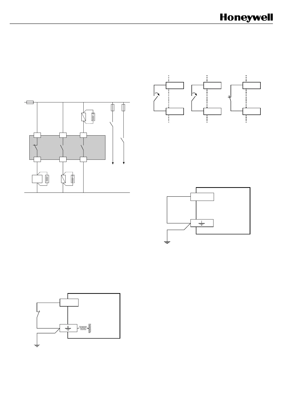
4.2.6 Use of auxillary N.C. contacts
(pins 1 and 2 of receiver signal plug)
Never use this contact alone for machine
shutdown.
These contacts can be used:
- either for indication of the stop signal from the barrier
- or as redundant complement to the main stop chain.
Machine
stopping
circuitry
K2
FF-SB14R
*
5
K1
62
1
4
K2
3
PLC
K1
Auxiliary
contact
*Additive resistor to increase the current up to 50 mA
at least. PLC: Programmable Logical Controller. The
partial example here being more appropriate for ac
power. See § 4.2.8 for correct interfacing of K1 and
K2.
4.2.7 Test input
Principle
Interruption (by a contact) of the electrical connection
between terminals EARTH and (3) of the power supply
plug sets off the barrier even if the beams have not
been broken.
Diagram - Operation
FF-SB14R
supply plug
3
The barrier only functions when connection (3) -
EARTH has been made.
Interruption of the connection (3) - EARTH causes:
the opening of the machine stop contacts and the
closing of the auxiliary contacts:
4
3
FF-SB14R - signal plug
1
2
6
5
Once connection (3) - EARTH has been broken (tmin
= 50 mS), it is enough to check that the relays,
controlled directly by the outputs of the FF-SB14, have
switched satisfactorily.
Warning: if the test function is not being used, then
do not forget to make the connection (3) - EARTH in
the supply plug.
FF-SB14R
supply plug
3
FSB14_25
FSB14_26
FSB14_27
FSB14_28

 Loading...


