107026-11-EN FR26 ROW 302 Printed in France 17
4.3 Electrical connection for
metal connector versions
(DIN 43652)
- FF-SB14E/R❏❏❏-S2❏ versions: connection by
crimped terminals (not to be welded) for supply-and-
signal plugs.
Recommended crimping tool: FA 0100-164.
Removal tool: FG 0300-146.
- Do not weld the terminals
- Do not use any other crimping tool than the
recommended one. Particularly, the use of engineer’s
pliers may generate bad contacts which may cause
troubles in case of important vibrations (see § 9.3).
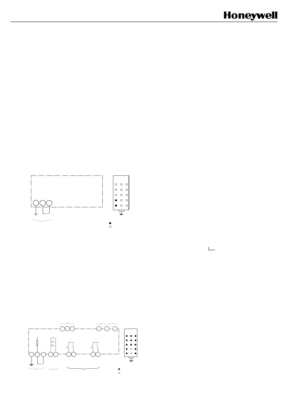
4.3.1 Emitter supply plug
(FF-SB14E❏❏❏
❏❏❏❏❏❏
❏❏❏-S2❏
❏❏
❏) (see § 4.3.3)
Connection drawing
ABC
1
2
3
4
5
A4
PE
A5
U~
Supply voltage
+
-
connected
not connected
PE EARTH
Note: Earth connection: cable section should be at
least equal to the supply cable section (refer to
EN 60204), and cable length should be as short as
possible. In order to get the specified noise immunity,
the earth terminal must be connected to the main
earth of the machine.
4.3.2 Receiver supply and signal plug
(FF-SB14R❏❏❏
❏❏❏❏❏❏
❏❏❏-S2❏
❏❏
❏) (see § 4.3.3)
Connection drawing
• load features: Umax = 250 Vac, I max = 2 A,
Pmax = 500 VA
Supply
PE
A4
A5
Time
delay
U~
Auxiliary
contacts *
+-
C3 C5 A3
ABC
1
2
3
4
5
Connected
EARTH
Safety
contacts *
B2
A1
A2
Monito-
ring /
reset
Beam
status
C4
C5
Test
input
B3
X1NC
X2NC
X1NO
X3NO
C2
X2NO
C1
X3NC
B1
X3NC
Not connected
A1, A2: 2 NC contacts in parallel for auxiliary use (see
§ 4.3.5)
B1, B2 and C1, C2: 2 NO safety contacts (see
§ 4.3.4)
B3, C4, C5 (test input): if the connection between
terminals C4/C5 or C4/B3 is set, the barrier operates
correctly (see § 4.3.7)
C3, C5: monitoring of Final Switching Devices
(see § 4.3.8 and 4.3.9).
A3, C5: beam status output (see § 4.3.6).
Note: Earth connection: cable section should be at
least equal to the supply cable section (refer to
EN 60204), and cable length should be as short as
possible. In order to get the specified noise immunity,
the earth terminal
must be connected to the main
earth of the machine.
Warning: If test function is not set, there must
be a connection between C4/C5 or C4/B3.
Without this electrical connection, the barrier
remains in permanent default state (see § 4.3.7).
Remark: X1, X2 and X3 relays are special safety
relays with mechanically linked contacts (guided
contacts).
For optimum operation, particularly low voltage,
minimum switching current is 50 mA. Increase current
with additional resistors, where necessary to maintain
minimum current level.
4.3.3 Electrical power supply
Supply voltage on A4-A5, are:
FF-SB14E/R❏❏❏-S2❏
K: 120/240 Vac
+10%, -20%
(automatic switching)
48-62 Hz, 8 VA per unit
4: 24 to 48 Vdc, ±15 %,
8 W per unit
Notes:
1/ For Vdc versions, the supply connection is the
following: terminal A4: +
terminal A5: -
However, the FF-SB14 is protected against reversed
polarity thanks to a rectifier.
2/ In order to get the specified immunity to electrical
noise, the earth terminal must be connected to the
main earth of the machine.
3/ Additional protection fuse on the power line:
- 500 mA (for 120 Vac mains) or 400 mA (for 240 Vac
mains) on both emitter and receiver.
- 500 mA (for 24 Vdc mains) on both emitter and
receiver.
FSB14_31
FSB14_32

 Loading...


