40 107026-11-EN FR26 ROW 302 Printed in France
9. List of devices, accessories and spares, and warranty
conditions
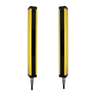
9.1 Barriers
FF-SB14 ❑ ❑❑ ❑ - ❑ 2 ❑
blank: 10 m (standard)
L: 3 m to 24 m (long range)
(1)
F: 6 m (filtered)
blank: plastic connector
(DIN 43651)*
S: metal connector
(DIN 43652)*
E/R: Emitter and
Receiver
E: Emitter
R: Receiver
04: 400 mm
06: 600 mm
08: 800 mm
10: 1000 mm
12: 1200 mm
14: 1400 mm
K: 120/240 Vac
4: 24 Vdc to 48 Vdc
(1) this model is available with metal connectors only
Note: the number of contacts available on the DIN 43651 plastic connector does not allow the detection field status
output, FSD monitoring input and start / restart interlock programming to be performed by the unit.
* DIN 43651: Test input only
DIN 43652: Test/monitoring input, detection field status output, programmable start / restart interlock.
One system includes: emitter, receiver, 2 RC circuits as well as electric connection plugs.
9.2 Accessories
(to be ordered separately); see page 7.
Mounting accessories:
FF-SBZS5000
Kit of 2 "Omega" supports with antivibration inserts
FF-SBZS6000 Kit of 2 fixed brackets with antivibration inserts
FF-SBZS7000 Kit of 2 rotatable brackets with antivibration inserts
FF-SBZS8000 Kit of accessories for direct mounting
idem FF-SBZS6000 but without the brackets
(includes 8 screws + 8 nuts + 16 washers + 8 antivibration inserts + 8 metal hubs)
Deflection mirrors:
FF-SBSMIR❏❏
❏❏❏❏
❏❏
Deflection mirror with adjustable brackets
Nominal protected height in dm (04 to 16)
FSB14_65
 Loading...


