7
FSL100 Operation
7.1 The Display LEDs
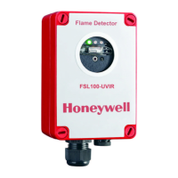
The FSL100 series flame detectors have 3 LEDs on the display:
Steady green: powered up and in normal operation
Steady yellow: fault (blinking yellow: repeated self-test after a self-test fault)
Steady red: alarm
7.2 Normal Operation
The green LED is on when power is applied and the detector is in normal operation.
Fire Alarm
The green normal operation LED turns off and the red alarm LED turns on whenever the detector senses an alarm condition
and (under default settings) the alarm will remain latched (held on) until the event is cleared and either the alarm is reset at the
controller or the detector’s power is cycled.
Alternatively, if the latch setting has been changed to ‘unlatched’ the detector will return to normal operation once the alarm
trigger event has been removed.
Note: Optional alarm system relay outputs may be triggered during an alarm condition.
7.3 Fault Conditions
The yellow and green LEDs are illuminated when a fault condition occurs. The yellow LED turns off as soon as the fault is
cleared.
The green and yellow LEDs turn off and the red LED turns on if an alarm occurs during a non-critical fault condition (i.e. during
an IR or UV lamp test).
A blinking yellow LED shows that a self-test is in progress. The LED will become steady yellow if the FSL100 repeatedly fails
self-test.
7.4 Relay Outputs
The flame detector has 2 relay outputs:
1. Alarm relay (SPDT) that can be used to operate an alarm or relay controlled event. It can be changed from Latching
(default) to Unlatched. A latched alarm can be reset by using controller software or by cycling the detector power off and
on.
2. Fault relay (SPDT). The fault relay is energized when the detector is powered up and will be de-energized in the event of a
fault. The fault relay is non-latching.
7.5 Analogue Output 0–20 mA (Stepped, Sinking, Non-Isolated)
The analogue output has the following possible values:
0 mA power fault / microprocessor fault
2 mA optical fault
4 mA normal operation
20 mA Alarm
The output defaults to 20 mA if, during a fault, the FSL100 detects a fire.
7.6 Self-Testing
The FSL100 carries out a Power On Self Test (POST), and the 3 LEDs will flash sequentially until it is completed (10 Seconds)
The LED sequence is replaced by a steady green LED If the detector passes the test.
While powered up, an optical self-test is periodically and automatically executed to monitor the electronics and the sensor(s).
During this short test the yellow LED may flash and the FSL100 outputs are temporarily inhibited. The test may repeat several
times if a sensor fails the optical self-test.
The yellow fault LED will be steady and the fault relay will de-energize if the fault condition remains after the repeated self-tests.

 Loading...

