16 LCD-SLP Product Installation Document — P/N LS10045-000GF-E:E 12/16/2019
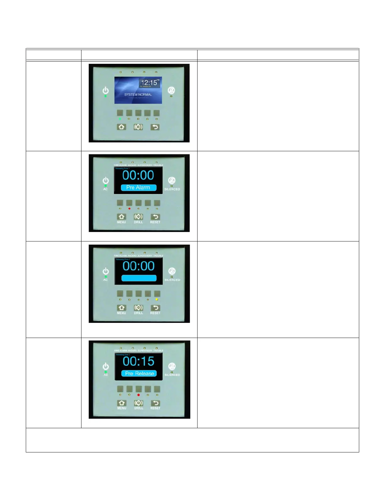
5.2 LCD-SLP Releasing Zone Screens for Releasing Operation
Table 5.2.1 lists the LCD-SLP screens that show the E3 Series Releasing operation on the LCD-SLP display panel.
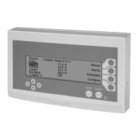
LEDs Display Description
Standby
Figure 5.2.1 Standby Condition
When the System is at the Standby stage, the following
occurs:
• The LED shows the Standby condition.
• The Standby LED lights steady GREEN.
• System Normal appears on the display.
Pre-Alarm
Figure 5.2.2 Pre-Alarm LED Activated
If only one alarm device in the Releasing Zone goes into
alarm, it does not trigger the Pre Release timer, but the
following occurs:
• The alarm device activates a Pre Alarm state.
• The Pre Alarm LED changes to steady RED.
• Pre Alarm appears on the display.
(See Note 1 in Table 5.2.1).
Abort
Figure 5.2.3 Pre-Alarm Abort LED
Activated
If the Releasing Zone aborts before the Release stage,
after you press the Abort switch the following occurs:
• The Abort LED turns on steady YELLOW.
• Abort appears on the display.
Pre-Release
Figure 5.2.4 Pre-Release LED Activated
If more than one device in the Releasing Zone goes into
alarm, it triggers the Pre-Release Timer and the following
occurs:
• Starts the Pre Release Timer.
• The Pre Release LED lights steady RED.
• Pre Release appears on the display.
(See Note 1 in Table 5.2.1)
Table 5.2.1 LCD-SLP, Releasing Zone Screens
STANDBY PRE-ALRM P-RELEASE RELEASE ABORT
FIRE ALARM HAZARD SUPERVISORY TROUBLE
AC SILENCED
MENU DRILL RESET
STANDBY PRE-ALRM P-RELEASE RELEASE ABORT
Abort
STANDBY PRE-ALRM P-RELEASE RELEASE ABORT
STANDBY PRE-ALRM P-RELEASE RELEASE ABORT
 Loading...