15
APPENDIX C – DIGITAL LOAD MANAGEMENT
(DLM) MODULES
The load controller can operate up to four separate DLM’s, each
one connected the same way as below.
The NEMA 3R Enclosure of the DLM module can be installed •
indoors or outdoors. If mounting outdoors the enclosure MUST
be orientated with the drain hole at the bottom.
The DLM module is fitted with conduit knockout locations. •
These knockout locations are the only locations that conduit
should be attached to the enclosure. A grounding stud is
provided inside the enclosure in order to ground the conduit.
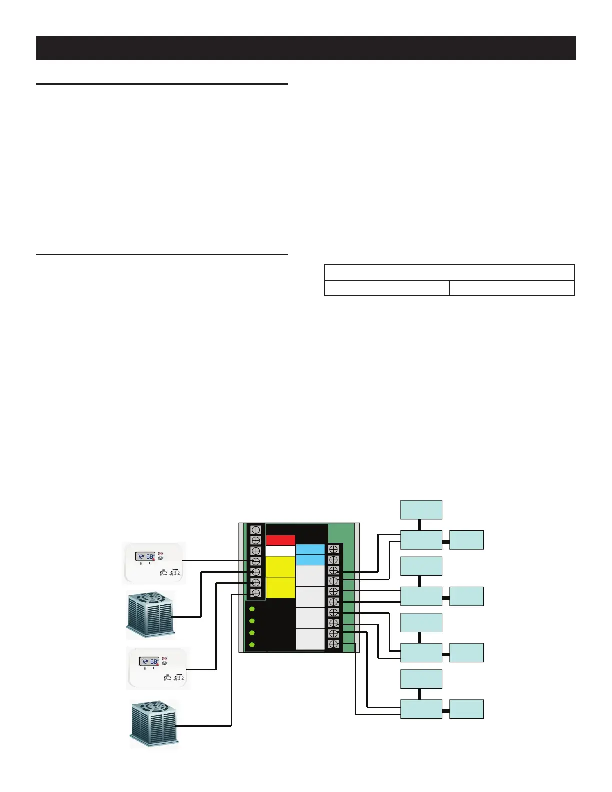
CONNECTING LOAD SHED MODULE (LSM) CONNECTIONS
The LSM can control an air conditioner (24 Vac) directly or
a separate contactor (120 Vac) which can control any load
connected to it (see Figure).
Sequence of Operation
The 4 green status LEDs will indicate when a load priority level is
enabled.
All loads are enabled when the transfer signal is off. (ATS in •
Utility position).
If the transfer signal is pulled low (Active)•
All loads are enabled until an overload is detected•
When an overload is detected all loads are disabled•
After 5 minutes priority 1 loads are enabled.•
After another 30 seconds priority 2 loads are enabled•
After another 30 seconds priority 3 loads are enabled•
After another 30 seconds priority 4 loads are enabled •
If an overload is detected within 30 seconds of a level being
enabled, all loads are disabled again and the sequence repeats.
However, the level that caused the overload and all levels higher
will not be enabled again for 30 minutes.
Control of Air Conditioner Load
1. Route the thermostat cable (from the furnace/thermostat to
the outdoor air conditioner unit) to the transfer switch.
2. Connect the wire to the terminal strip terminals (Air 1) on
the LSM as shown in Figure 2.2. These are normally closed
contacts which open upon load shed conditions. Route
thermostat wire away from High voltage wires.
3. If required, connect the second air conditioner to the terminal
strip terminals (Air 2).
Contact Ratings
Air 1 & 2 24 VAC, 5.0 Amps Max
NOTE:
These instructions are for a typical air conditioner
installation. Control of heat pump and 2-stage air
conditioners will require special connections.
Control of a Separate Contactor
A separate contactor relay module can be purchased from the
manufacturer. If a different relay is used it must have a 120 Vac
coil voltage. The LSM supplies fused (5A) 120 Vac to energize the
coils of the relay contactors (contactor 1, 2, 3 or 4).
1. Mount the contactor module and connect the load to the main
contacts.
0 Ground
194 +12V
23 Transfer
T1
NEUTRAL
AIR 1
AIR 2
CONTACTOR
1
CONTACTOR
2
CONTACTOR
3
CONTACTOR
4
Priority 1
Priority 2
Priority 3
Priority 4
0 Ground
194 +12V
23 Transfer
T1
NEUTRAL
AIR 1
AIR 2
CONTACTOR
1
CONTACTOR
2
CONTACTOR
3
CONTACTOR
4
Priority 1
Priority 2
Priority 3
Priority 4
Contactor #1 Load #1
Supply
Coil wires
Contactor #2 Load #2
Supply
Contactor #4 Load #4
Supply
Contactor #3 Load #3
Supply
Load Shed Module Connections
Appendix C
 Loading...