2 Power Supply Rack Extension Kit # 51-52-33-149
12/2018
Step Action
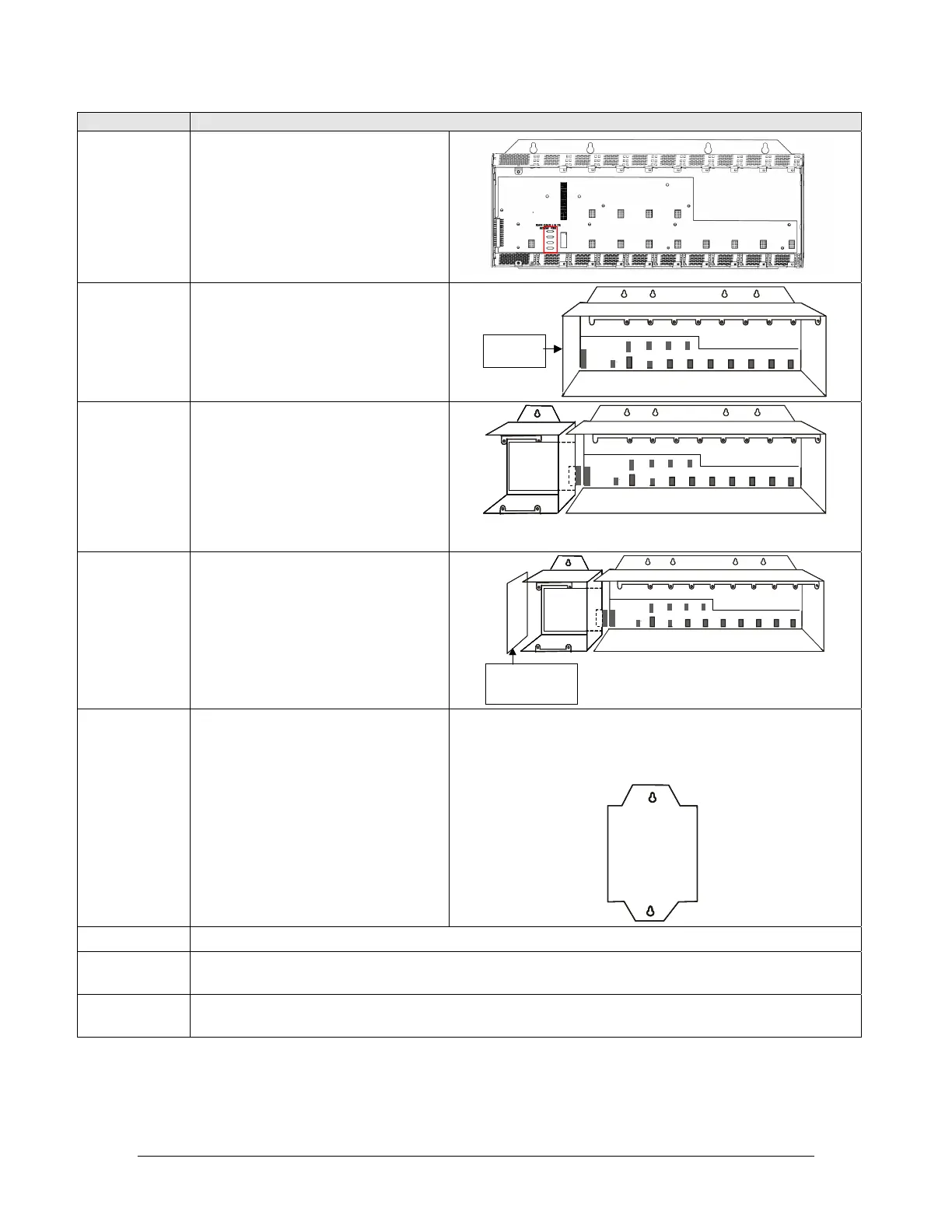
3
900R12-0200 (Standard Rack) can
be converted to 900R12R-0200
(Redundant power Supply). Locate
resistors R3, R4, R5 and R6 on the
I/O rack backplane. Cut and
remove
the resistors, replace end cap.
R3
R4
R3
R4
R3
R4
4
Remove the screws from the
outside of the I/O rack side plate.
Retain the side plate.
JP21
I/O Rack
Side Plate
JP21JP21
I/O Rack
Side Plate
5
Attach the PS extension rack to
the I/O rack with 4 of the screws
(SEMS M3 X 5.0 mm long)
provided in the kit.
Make sure that J3 on the PS
extension rack backplane
meshes with JP21 on the I/O
rack backplane.
J3
JP21
J3J3
JP21
6
Attach the side plate previously
removed from the I/O rack to the
PS extension rack using the 6
screws (Flat Head M3 x 6.0 mm
long) provided in the kit.
Note that the countersunk holes in
the plate should face outward.
J3
JP21
I/O Rack
Side Plate
previously removed
J3
JP21
J3J3
JP21
I/O Rack
Side Plate
previously removed
7
You will need to drill two mounting
holes (same size mounting holes
as the main rack) for the 900RPE
rack.
Place the updated rack in
position and mark the 2
mounting hole locations (top
and bottom of rack of the 900
RPE extension).
Remove the rack and drill the
mounting holes.
900RPE Rear
Mounting Plate
900RPE Rear
Mounting Plate
8 Re-install the Power Supply, CPU or Scanner and I/O modules.
9
If available, install the new Power Supply Module and Power Status Module into the 900RPE
rack.
10
Mount the updated rack assembly and connect a separate power source with disconnect to the
new power supply.

 Loading...


