Installation NAC Circuit Wiring
22 HPFF12 NAC Expander — P/N 53576:B3 10/1/2018
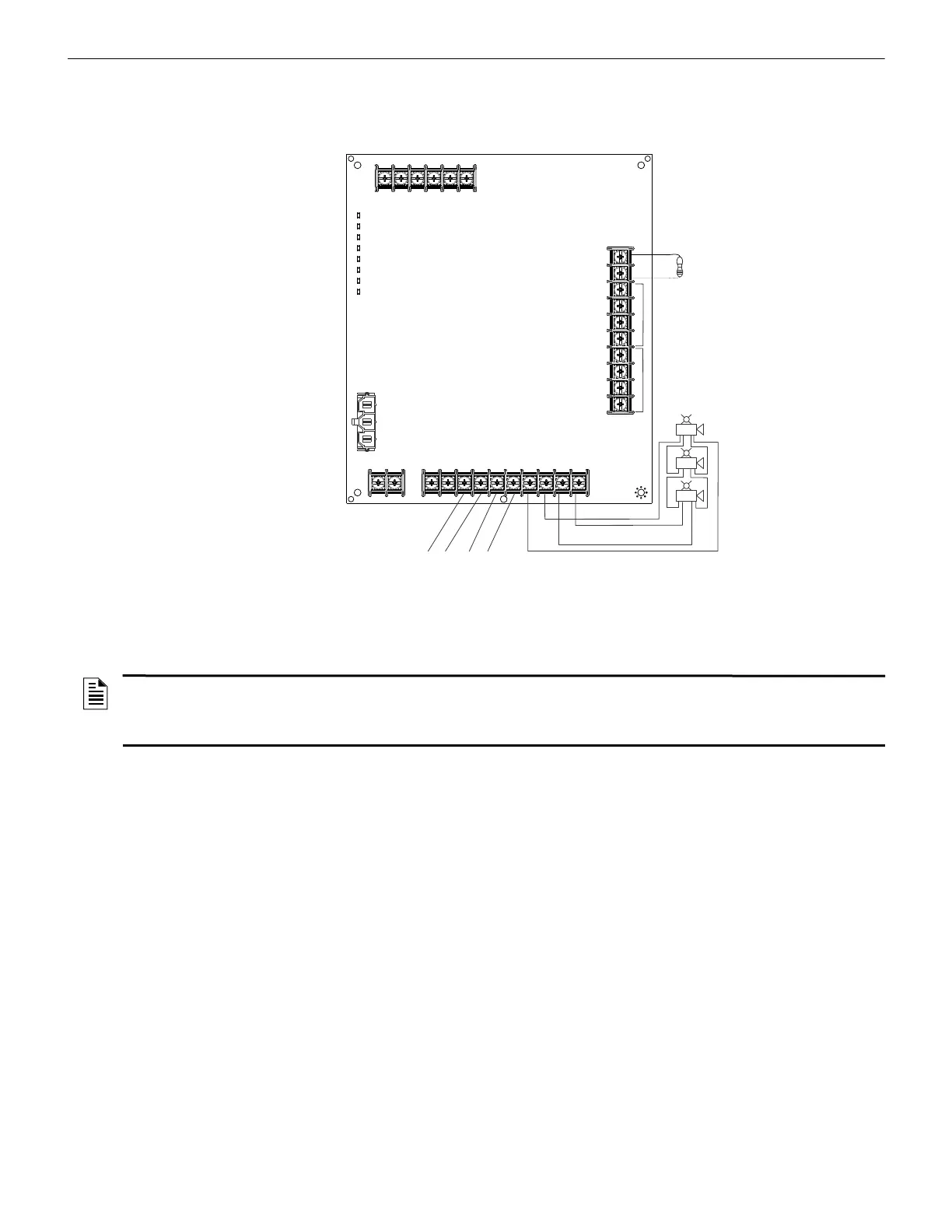
2.3.3 Mixing Class B and Class A NACs
Figure 2.12 shows two NACs configured for Class B (Style Y) and one NAC configured for
Class A (Style Z).
NOTE: NAC 1 and NAC 2 in
Class B (Style Y) - See
Section 2.3.1 for wiring.
NAC 3
H
P
F
F
1
2
N
A
C
C
l
a
s
s
A
w
i
t
h
B
.
w
m
f
Horn Strobe
Horn Strobe
Horn Strobe
Alarm Polarity
Shown
Note: NAC 3 in Class A;
no ELR required.
NAC 1
• Trouble on NAC1
will illuminate
LED1 SIG1 TRBL
• Trouble on NAC2
will illuminate
LED2 SIG2 TRBL
• Trouble on NAC3
will illuminate
LED3 SIG3 TRBL and
LED4 SIG4 TRBL
Reference Resistor
(Same as ELRs for
NAC 1 & NAC2)
NAC 2
Figure 2.12 Configuring Two Class B NACs and One Class A NAC on One HPFF
NOTES:
1. Typical ELRs for new installations can be 3.9k or 4.7k ohm.
2. The same gauge wire must be used if two conductors are connected to the same terminal of any terminal block.
3. Do not complete a continuous circuit around the screw terminal. There must be two separate wires on either side of the screw at the
terminal block. “T-tapping” is absolutely NOT ALLOWED.
 Loading...


