HPFF12 NAC Expander — P/N 53576:B3 10/1/2018 39
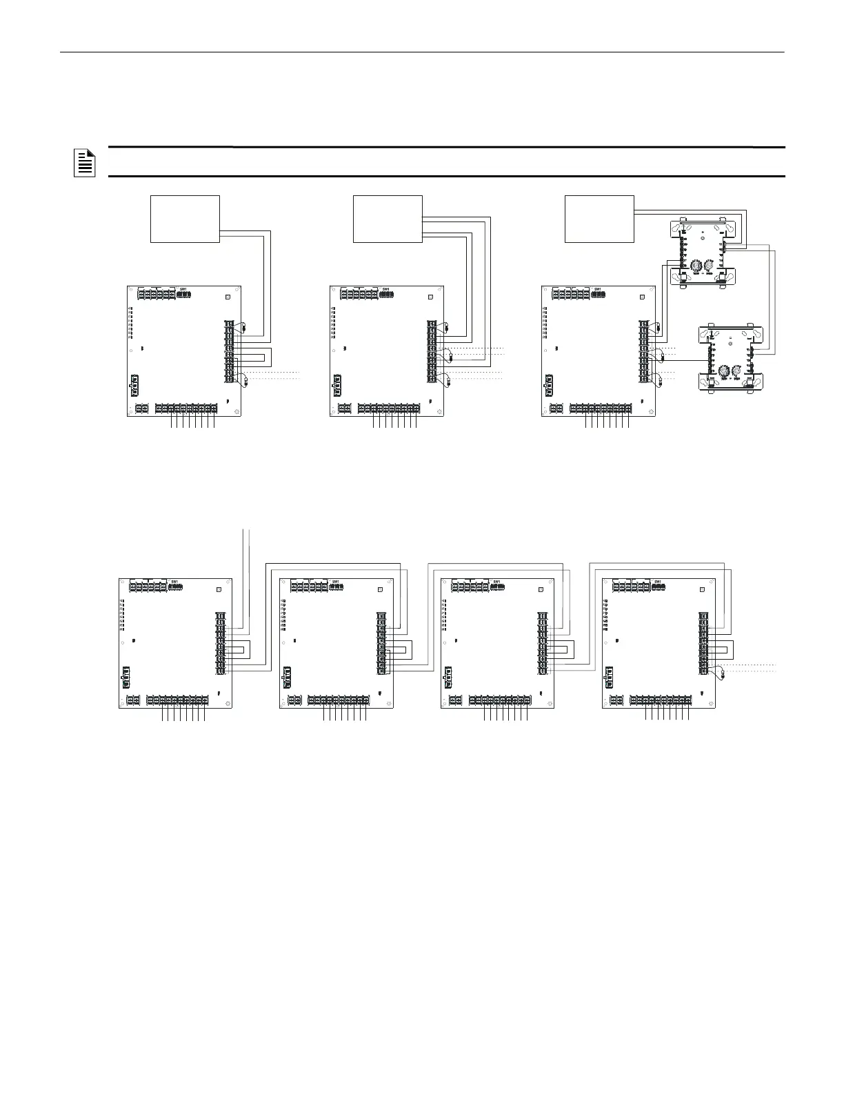
Connecting Multiple Units Applications
5.4 Connecting Multiple Units
Two or more HPFF12 and/or HPFF8 units can be connected to each other to provide additional NAC extenders for a system; see wiring
in Figures 5.5–5.10 and in the HPFF8 manual PN 53499. Maintain separation of power-limited and non-power limited wiring as dis-
cussed in Section 2.5, “Power-Limited Wiring Requirements”.
Notes for Figures 5.5–5.10:
1.
The FACP’s NAC output must be regulated (not Full Wave Rectified [FWR]) if the HPFF is programmed for Sync Generator.
2. The number of possible units that can be interconnected depends on the current capability of the FACP output. Each HPFF12 input
draws 12.26 mA at 24 VDC.
3. The total line impedance for interconnected units cannot be such that it creates a voltage drop > 2 VDC.
Zline total =2V/(1 Unit + 1 ELR)
Example: Zline total = 2V/(12.26 mA + (24-2)/4.7K) =118.1 ohms
NOTE: Multiple units should not be connected in a “daisy chain” fashion. DO NOT connect a NAC output of one unit to the initiating device
signal input of the next unit. The synchronization signal will not pass unimpeded through multiple units with this wiring method.
TB3
TB4TB1
TB2
SW2
LEDs
REF+ REF– + IN – IN
+ OUT
– IN
+ OUT+ OUT
+ IN
– OUT
SIGNAL 1
SIGNAL 2
BATT+ BATT–
A+
N/O
N/C C OMM
N/O
N/C COMM
AC FAIL
TROUBLE
J1
J2
1L1 1L2 2L1 2L2
3L1 3 L2
4L1 4L2A–
TB3
TB4TB 1
TB2
SW2
LEDs
REF+ REF– + IN – IN + OUT – IN + OUT+ OUT + IN – OUT
SIGNAL 1
SIGNAL 2
BATT+ BATT–
A+
N/O
N/C COMM
N/O
N/C COMM
AC FAIL
TROUBLE
J1
J2
1L1 1L2 2L1 2L2
3L1 3L2
4L1 4L2A–
LEDs
REF+ REF– + IN – IN
+ OUT
– IN
+ OUT+ OUT
+ IN
– OUT
SIGNAL 1
SIGNAL 2
A+
N/O
N/C COMM
N/O
N/C COMM
AC FAIL
TROUBLE
J1
J2
1L1 1L2 2L1 2L2
3L1 3 L2
4L1 4L2A–
FACP
Remote Sync
or NAC Output
conventional
to NACs
ELR or to
next units
conventional
to NACs
ELRs or to
next units
FACP
NAC Outputs
non-silenceable
silenceable
FACP
SLC
NAC Outputs
to NACs
Control Module
(non-silenceable point)
ELRs
or to
next
units
Relay Module
(silenceable
point)
HPFF12 Sync
Generator or
Pass-Through
(Slave)
HPFF12 Sync
Generator or
Pass-Through
(Slave)
(filtered if
FWR input)
HPFF12 Sync
Generator or
Pass-Through
(Slave)
(filtered if
FWR input)
NAC Outputs
NAC Outputs
Figure 5.5 Typical System Connections
TB3
TB4TB1
TB2
SW2
LEDs
REF+ REF– + IN – IN + O UT – IN + OUT+ OUT + IN – OUT
SIGNAL 1 SIGNAL 2
BATT+ B ATT–
A+
N/O
N/C
COMMN/O
N/C
COMM
AC FAIL
TROUBLE
J1
J2
1L1 1L2 2L1 2L2
3L1 3L2
4L1 4L2A–
LEDs
REF+ REF– + IN – IN + O UT – IN + OUT+ OUT + IN – OUT
SIGNAL 1
SIGNAL 2
BATT+ BATT–
A+
N/O
N/C
COMMN/O
N/C
COMM
AC FAIL
TROUBLE
J1
J2
1L1 1L2 2L1 2L2
3L1 3L2
4L1 4L2A–
LEDs
REF+ REF– + IN – IN + O UT – IN + OUT+ OUT + IN – OUT
SIGNAL 1
SIGNAL 2
A+
N/O
N/C
COMMN/O
N/C
COMM
AC FAIL
TROUBLE
J1
J2
1L1 1L2 2L1 2L2
3L1 3L2
4L1 4L2A–
TB3
TB4TB1
TB2
SW2
LEDs
REF+ REF– + IN – IN
+ OUT
– IN
+ OUT+ OUT
+ IN
– OUT
SIGNAL 1
SIGNAL 2
BATT+ BATT–
A+
N/O
N/C
COMMN/O
N/C
COMM
AC FAIL
TROUBLE
J1
J2
1L1 1L2 2L1 2L2
3L1 3L2
4L1 4L2A–
HPFF12
Pass-Through
(Slave)
(filtered if
FWR input)
Remote Sync or NAC
Output with sync
Figure 5.6 System Sync Connections
NAC Outputs
to NACs
to NACs to NACs
to NACs
NAC Outputs NAC Outputs
HPFF12
Pass-Through
(Slave)
(filtered if
FWR input)
HPFF12
Pass-Through
(Slave)
(filtered if
FWR input)
HPFF12
Pass-Through
(Slave)
(filtered if
FWR input)
ELR or to
next unit
 Loading...


