40 HPFF12 NAC Expander — P/N 53576:B3 10/1/2018
Applications Connecting Multiple Units
w
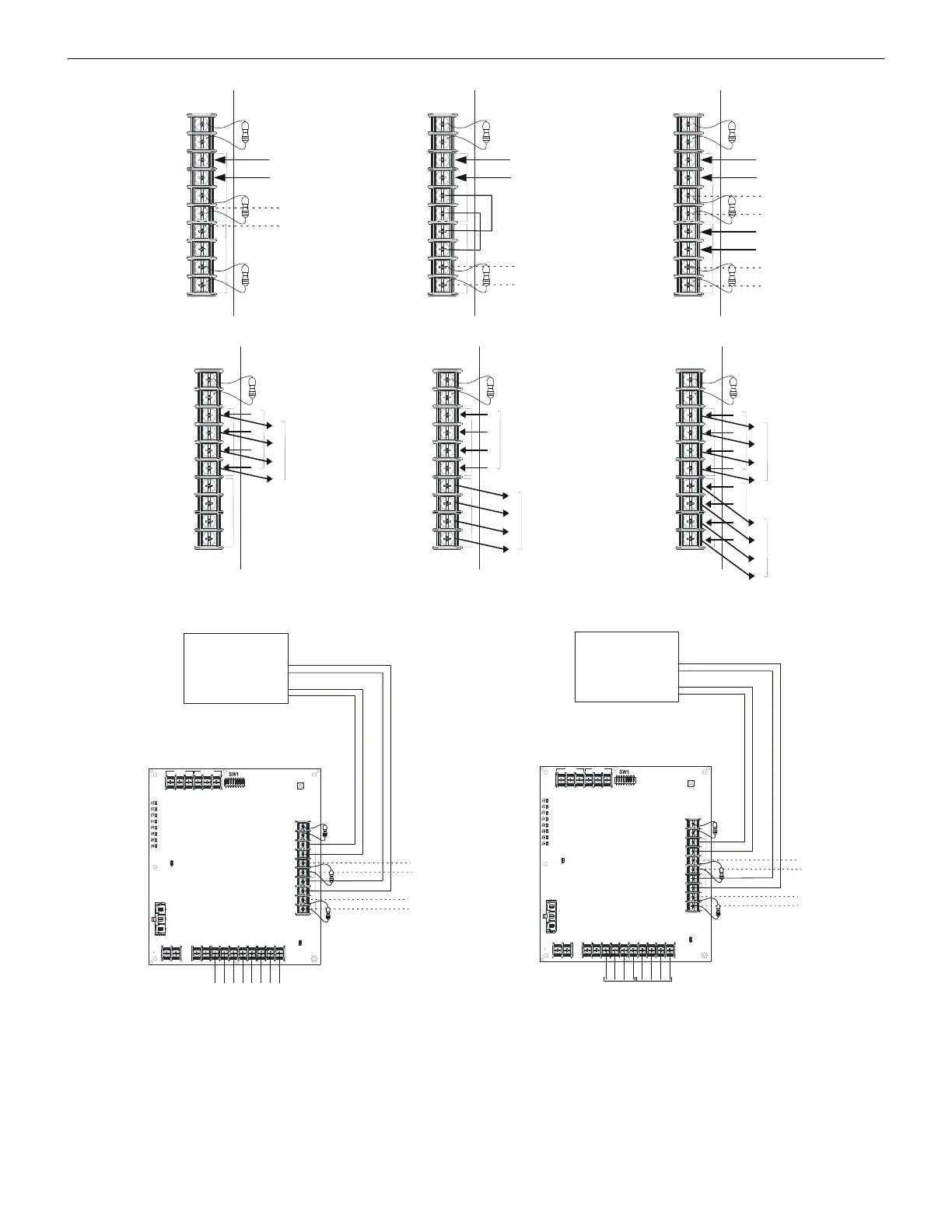
Notes for Figures 5.5–5.10:
1. The FACP’s NAC output must be regulated (not Full Wave Rectified [FWR]) if the HPFF is programmed for Sync Generator.
2. The number of possible units that can be interconnected depends on the current capability of the FACP output. Each HPFF12 input
draws 12.26 mA at 24 VDC.
3. The total line impedance for interconnected units cannot be such that it creates a voltage drop > 2 VDC.
Zline total =2V/(1 Unit + 1 ELR)
Example: Zline total = 2V/(12.26 mA + (24-2)/4.7K) =118.1 ohms
Figure 5.9 Split Alarm Connections Figure 5.10 Selective Silencing Connections
+
-
TB3
REF+ REF– + IN – IN
+ OUT
– IN
+ OUT+ OUT
+ IN
– OUT
SIGNAL 1
SIGNAL 2
+
-
TB3
REF+ REF– + IN – IN
+ OUT
– IN
+ OUT+ OUT
+ IN
– OUT
SIGNAL 1
SIGNAL 2
REF+ REF– + IN – IN
+ OUT
– IN
+ OUT+ OUT
+ IN
– OUT
SIGNAL 1
SIGNAL 2
in from FACP or
previous HPFF12
ELR or out
to next unit
in from FACP or
previous HPFF12
ELR or out
to next unit
in from FACP or
previous HPFF12
in from FACP or
previous HPFF12
ELR or out
to next unit
ELR or out
to next unit
Ref +
Ref -
In #1 +
In #1 -
Out #1 +
Out #1 -
In #2 +
In #2 -
Out #2 +
Out #2 -
Ref +
Ref -
In #1 +
In #1 -
Out #1 +
Out #1 -
In #2 +
In #2 -
Out #2 +
Out #2 -
Ref +
Ref -
In #1 +
In #1 -
Out #1 +
Out #1 -
In #2 +
In #2 -
Out #2 +
Out #2 -
Figure 5.7 Class B Input Connections
TB3
REF+ REF– + IN – IN
+ OUT
– IN
+ OUT+ OUT
+ IN
– OUT
SIGNAL 1
SIGNAL 2
TB3
REF+ REF– + IN – IN
+ OUT
– IN
+ OUT+ OUT
+ IN
– OUT
SIGNAL 1
SIGNAL 2
REF+ REF– + IN – IN
+ OUT
– IN
+ OUT+ OUT
+ IN
– OUT
SIGNAL 1
SIGNAL 2
+
-
+
-
+
-
+
-
+
-
+
-
+
-
+
-
In from FACP or
previous FF23
Out to next
HPFF12 or
return to FACP
In from FACP or
previous HPFF12
Out to next HPFF12
or return to FACP
In from FACP or
previous HPFF12
In from FACP or
previous HPFF12
Out to next HPFF12
or return to FACP
Out to next HPFF12
or return to FACP
Figure 5.8 Class A Input Connections
TB3
TB4TB1
TB2
SW2
LEDs
REF+ REF– + IN – IN + OUT – IN + OUT+ OUT + IN – OUT
SIGNAL 1
SIGNAL 2
BATT+ BATT–
A+
N/O
N/C
COMM
N/O
N/C
COMM
AC FAIL
TROUBLE
J1
J2
1L1 1L2 2L1 2L2
3L1 3L2
4L1 4L2A–
conventional
NAC Outputs
to NACs
ELRs or to
next units
FACP
HPFF12 Sync
Generator
(paired outputs
in any
combination of
temporal or a
sync protocol)
NAC Outputs
ELRs or to
next units
TB3
TB4TB1
TB2
SW2
LEDs
REF+ RE F– + IN – IN
+ OUT
– IN
+ OUT+ OUT
+ IN
– OUT
SIGNAL 1
SIGNAL 2
BATT+ BATT–
A+
N/O
N/C C OMM
N/O
N/C COMM
AC FAIL
TROUBLE
J1
J2
1L1 1L2 2L1 2L2
3L1 3L2
4L1 4L2A–
conventional
FACP
NAC Outputs
silenceable
silenceable
HPFF12
Pass-Through
(Slave)
(filtered if
FWR input)
NAC Outputs
to NACs
ELRs or to
next units
ELRs or to
next units
silenced
pair
silenced
pair
 Loading...


