HPZC10*
33-00360EF—05 6
TROUBLESHOOTING
Valve Fuse Protection
The Hydronic Zone Valve panels come equipped with
automatically resettable fuses on each valve output. This
fuse will trip when a load of 3.7 Amps or higher is applied.
Should one of the valves in a system fail shorted, the
panel’s Power Transformer Fuse will be protected and all
other zones in the system will remain operational.
It is recommended that power be removed from the
Hydronic Zone Valve Panel, before replacing a faulty zone
valve. This will accelerate the time required for the fuse to
automatically reset and return fully to its initial state.
The following steps can be used to detect if a valve fault
has occurred:
• Open panel cover
• Slide Priority Switch position to OFF
• Jumper terminals 3 and 4 on the suspect zone valve
output
• Give zone thermostat a call for heat
• If the thermostat LED is ON and Valve LED is OFF, the
panel’s fuse has tripped (valve fault – short).
• Slide the Priority Switch position back to its initial
position.
NOTE: Before replacing a faulty valve, remember to
remove power from the zone panel.
Status Label
Fig. 16.
This panel provides a status indicator label which is
available both when the panel cover is in place and
removed. Descriptions of the indicator LED's are shown
below:
T-stat Call
LED's indicate the thermostat associated with
that specific zone is calling for heat, with the exception of
when a priority zone call is active and the 60 minute
"Priority-Timer" has not expired. During this time, LED's on
Zone 2-6 will be turned off.
Valve Open
LED's indicate when a valve has been
energized and the end switch is closed or jumpered.
DHW Priority
LED indicates the priority zone is active and
calling. When DHW zone is active all other zone LED's will
be deactivated.
Power
LED indicates the transformer is powered.
Boiler and End Switch LED's indicate when each burner
relay is energized and calling for heat.
Table 2. Color Chart.
REGULATORY INFORMATION
This device complies with part 15 of the FCC rules.
Operation is subject to the following two conditions:
(1) This device may not cause harmful interference, and
(2) this device must accept any interference received,
including interference that may cause undesired
operation.
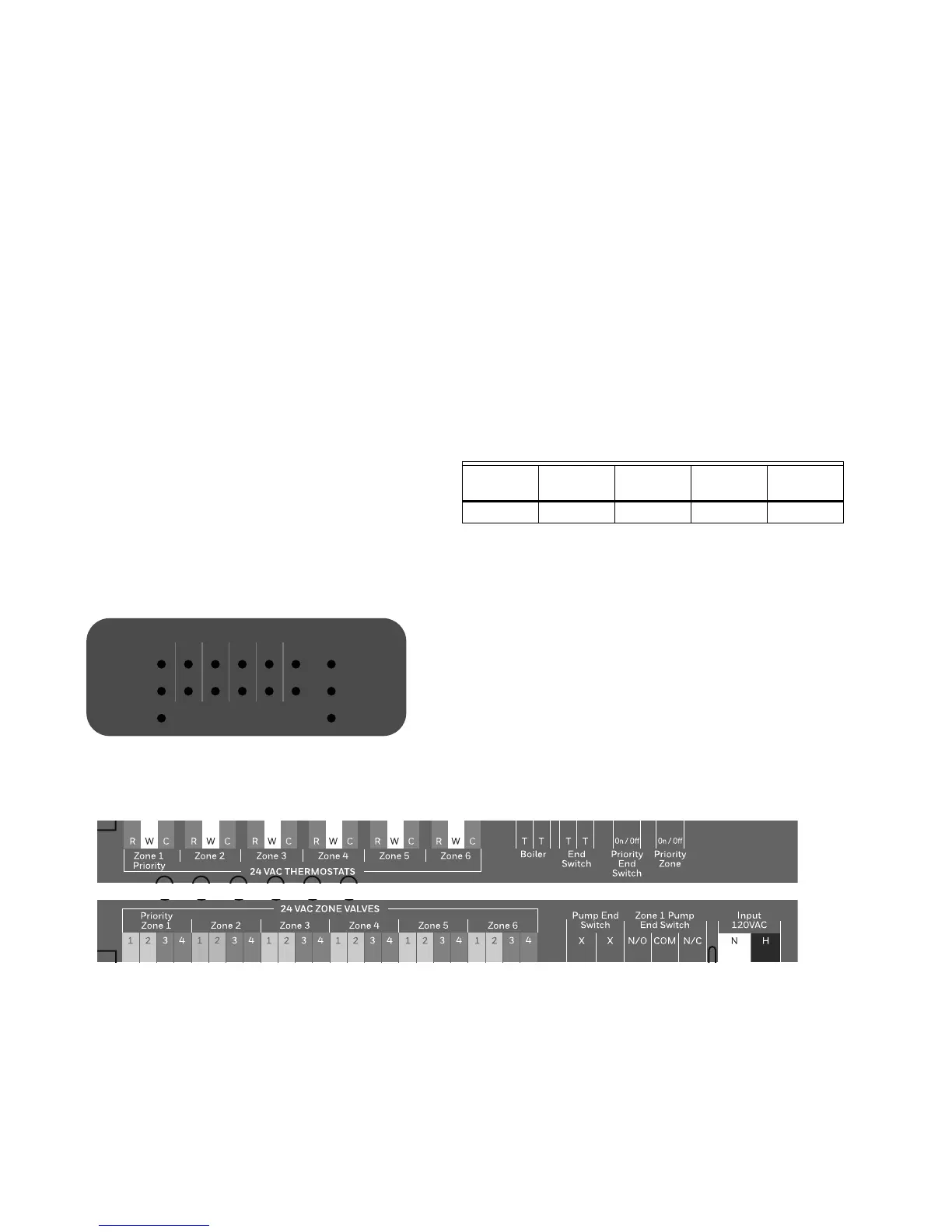
Mylar Cover
Fig. 17. Mylar cover.
Power
Boiler
End Switch
Zone
T-stat Call
Valve Open
DHW
Priority
123456
6ZONE VALVE CONTROLLERHPZC106
M37101
T-Stat Call Valve Open DHW Priority Power
Boiler & End
Switch
Blue Green White White Red

 Loading...


