800-16693 - A - 04/2014
Introducing the HRGX DVR | 11
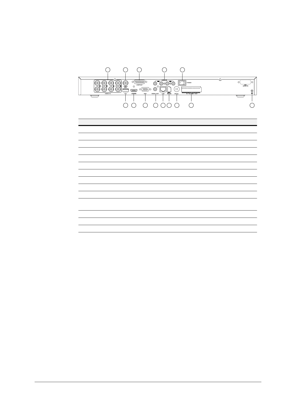
The following illustration shows the rear panel of the 8-channel HRGX DVR.
Figure 1-4 HRGX8 Rear Panel
No. Name Description
1 Video In BNC connectors for analog video input
2 Video Out BNC connectors for analog video output
3 USB Port Connects USB device (such as a USB mouse)
4 HDMI HDMI connector for high definition digital video output
5 Loop Out DB26 socket for independent video output
6 VGA Port DE15 socket for local video output
7 Audio In RCA connectors for audio input
8 Audio Out RCA connectors for audio output
9 Alarm In/Out Connector for alarm input/output
10 LAN Port RJ45 10M/100M Ethernet interface
11 RS-485 Connects RS-485 devices.
Connect D+ and D– terminals to R+ and R– terminals of PTZ receiver.
12 12V 12 V DC power input
13 Power Switch Switch for turning DVR on/off
14 GND Ground terminal (needs to be connected before DVR is turned on)
75
1 2
9
13
3 4 6 8
10
11 12 14

 Loading...