EasyManuals Logo

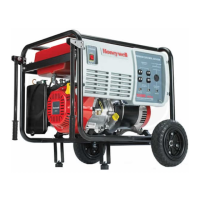
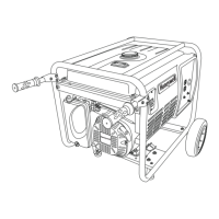
Honeywell HW7000EH User Manual

Honeywell HW7000EH
45 pages
To Next Page IconTo Next Page
To Previous Page IconTo Previous Page
Page #36 background imageLoading...
Page #36 background image
Wiring Diagram
30 www.honeywellgenerators.com HW7000EH Portable Electrical Generator Owner’s Manual
Wiring Diagram
FIGURE 41: HW7000EH Wiring Diagram
G
Y
W
X
GENERATOR
CONTROL PANEL
ENGINE
SPARK
PLUG
LOW OIL
SWITCH
IGNITION
COIL
ENGINE BLOCK
Y
Y
Bl
Bl
ENGINE
CONTROL
SWITCH
Bl
GROUND
TERMINAL
DUPLEX 5-20R
Y/G
SINGLE POLE
THERMAL
AC BREAKER
120V 20A
G
WX
FIELD
WINDING
MAIN
WINDING
EXCITER
WINDING
AVR
WR WLg Bu Bu
120 VAC
ALTERNATOR
Bl - Black
Bu - Blue
Br - Brown
B/W - Black / White
Gr - Green
Lg - Light Green
R - Red
Y - Yellow
Y/G - Yellow / Green
W - White
SINGLE POLE
THERMAL
AC BREAKER
120V 20A
NOTE: Alternator is mechanically
connected to the engine block
providing ground connection between
the engine block and alternator frame.
ON/OFF SWITCH PANEL
G
WX
DUPLEX 5-20R
G
WY
G
WY
MAIN
WINDING
Br WRBu
WRBu
Br
TWIST-LOCK
L14-30R
Gr
DUAL POLE
MAGNETIC
AC BREAKER
240V 30A
Bl
=
_
o
W
RECTIFIER
CIRCUIT
PROTECTOR
CHARGE
COIL
BATTERY
STARTER
MOTOR
M
Gr
W
W
B/W
120V AC
Hour Meter
Y
120 VAC
CONNECTOR
CONNECTOR
Y
OIL ALERT
SENSOR

Other manuals for Honeywell HW7000EH

Questions and Answers:

Question and Answer IconNeed help?

Do you have a question about the Honeywell HW7000EH and is the answer not in the manual?

Honeywell HW7000EH Specifications

General IconGeneral
BrandHoneywell
ModelHW7000EH
CategoryPortable Generator
LanguageEnglish

Related product manuals