ICON 100 SERIES USER GUIDE
EN2B-0002UK07 R0404
14
6. PARAMETER CONFIGURATION
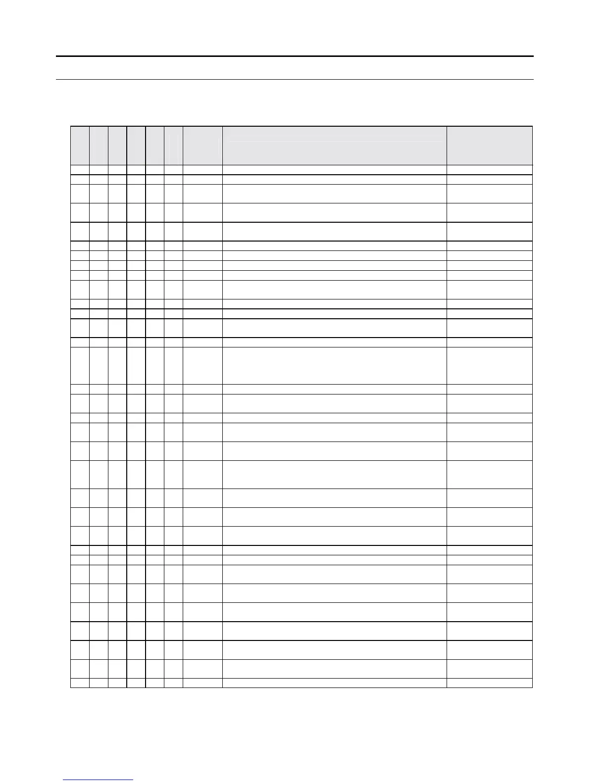
The configuration parameters and related limits or options are given in the table
below. A box without a ‘
’ symbol means that the corresponding controller does not
have that parameter.
111S
111SR
112S
112SR
132S
132SR
PARA-
METER
DESCRIPTION
LIMIT / OPTIONS
d1 Main setpoint (d3 … d4)
d2 Differential (hysterises) 0…+ 20
o
C
d3 Lower limit of main setpoint
-55…(d4)
o
C
-67…(d4)
o
F
d4 Upper limit of main setpoint
(d3)…+ 130
o
C
(d3) ... +266
o
F
d5
Minimum time interval between successive switching of the
compressor
0…999 s
d6 Max. temperature alarm differential 0...+50
o
C
d7 Maximum or minimum temp. alarm delay 0…99 min.
d8
Time interval between defrost cycles (refer to page 13)
1…999 h.
d9 Max Defrost Cycle time 1…999 min.
d10 Target defrost temperature
-60…+100
o
C
-76…+212
o
F
d11 Time period for supplementary defrost 0…99 min
d12 Defrost Recovery time 0…99 min.
d13 Compressor function during defrosting
0 = always OFF
1 = always ON
d14 Drain Down 0…99 min.
d15 Fan operation mode during normal controller function
0 = linked to the
compressor
operating mode
1 = always ON
d16 Fan activation delay at controller startup and after defrosting 0…99 min.
d17
Fan activation temperature at controller startup and after
defrosting
-60…+100
o
C
-76…+212
o
F
d19 Display Offset -20…+20
o
C
d20 2k NTC and PT1000 probe selection
0= PT1000
1= 2k NTC
d22 Unit of temperature measurement
0 =
o
Celsius
1=
o
Fahrenheit
d23 Compressor function during a probe failure
0 = always OFF
1 = always ON
2 = timed ON & OFF
d24 Compressor ON time during probe failure
0…99 min.
(do not set to "0")
d25 Compressor OFF time during probe failure
0…99 min.
(do not set to "0")
d26
Defrost via local control or remote access control (Genus
®
network)
0= Local
1= Remote
d27 Stub number when connected to Genus
®
network 0…99
d28 Case number when connected to Genus
®
network 0…9…A…U
d29 Connect to Genus
®
network
0 = off
1 = on
d30 Defrost start time 1 (SR models only)
00:00…23:50 hrs
(00…235)
d31 Defrost start time 2 (SR models only)
00:00…23:50 hrs
(00…235)
d32 Defrost start time 3 (SR models only)
00:00…23:50 hrs
(00…235)
d33 Defrost start time 4 (SR models only)
00:00…23:50 hrs
(00…235)
d34
First defrost cycle after controller startup (refer to page 13)
0= after 10 minutes
1= after d8 (hours)
d38 Minimum temperature alarm differential 0… 50
o
C
Table 3. Parameter Configuration
 Loading...


