JADE™ ECONOMIZER MODULE
3 63-2700—01
BEFORE INSTALLATION
Review the “Specifications” on page 2 before installing the The
JADE™ Economizer System.
When Installing This Product
1. Read these instructions carefully. Failure to follow them
could damage the product or cause a hazardous condi-
tion.
2. Check ratings given in instructions and on the product to
ensure the product is suitable for your application.
3. Installer must be a trained, experienced service
technician.
4. After installation is complete, check out product
operation as provided in these instructions.
INSTALLATION AND SETUP
The following installation procedures should be performed in
the order listed:
1. Mounting — see “Mounting” on this page.
2. Wiring — see “Wiring” on this page.
3. Interface and Programming overview – see page 11.
4. Setup and Configuration — see page 15
5. Checkout — see page 18.
Troubleshooting and Alarms begin on page 20.
MOUNTING
This section describes the mounting procedures for the
JADE™ Economizer module and the sensors.
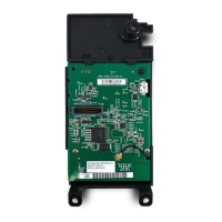
Economizer Module Location and
Mounting
IMPORTANT
Avoid mounting in areas where acid fumes or other
deteriorating vapors can attack the metal parts of the
module’s circuit board, or in areas where escaping
gas or other explosive vapors are present.
IMPORTANT
The module must be mounted in a position that allows
clearance for wiring, servicing, and removal.
Mount the Economizer module on any convenient interior
location using the two mounting holes provided on the
enclosure using #6 or #8 screws (screws are not provided and
must be obtained separately). Use the dimensions in Fig. 1 on
page 2 as a guide.
The Economizer module may be mounted in any orientation.
However, mounting in the orientation shown in Fig. 1 on page 2
permits proper viewing of the LCD display and use of the
keypad.
Sensor Location and Mounting
The JADE™ Economizer W7220 uses digital sensors for
control. The MAT
a
and OAT
b
sensors are 20k NTC sensors. A
MAT sensor is required for all applications and is mounted in
the mixed air section of a rooftop unit either directly to the
sheet metal using self tapping sheet metal screws or in the air
stream using the duct mounting kit.
Optional OAT, RAT
c
and DAT
d
Sylkbus sensors communicate
with the W7220 on the two-wire communication bus and can
either be wired using a two pin header or using a side
connector. Each Sylkbus sensor includes a two pin Euro
connector with the packaging. The SKU number of the Sylkbus
sensor is C7400S. All OAT, RAT and DAT sensors are the
same SKU number. The sensor is set for the appropriate type
of sensing using the three position DIP switch located on the
sensor. OAT position is OFF, OFF, OFF; RAT is ON, OFF, OFF
and DAT is OFF, ON, OFF. During installation the sensors are
set for the usage desired. See “Sylk Bus Sensor Wiring” on
page 6 for DIP switch details.
Once installed, a sensor can be changed to a different
application by simply changing the DIP switch setting.
a
MAT = Mixed Air Temperature
b
OAT = Outside Air Temperature
c
RAT = Return Air Temperature
d
DAT = Discharge Air Temperature
 Loading...