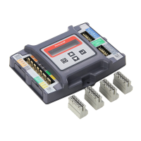
JADE™ ECONOMIZER MODULE
63-2700—01 4
Sensor Mounting
The sensors can be mounted directly on to the sheet metal of
unit or can be mounted in the air stream using the duct
mounting kit.
The kit contains a rod to hold the sensor in the duct, a flange to
secure the sensor rod to the duct wall and fill the hole and a
gasket to prevent air from leaking through the duct wall. See
Fig. 2.
The rod has slots for threading the wire to prevent loose or
hanging wire in the duct and can be adjusted for 6 or 12 inch
length. The flange has extended relief for ease of mounting.
See 3.
Fig. 2. Duct Mounting Kit (Part Nbr. 50053060-001).
Fig. 3. Duct Mounting Adjustments.
WIRING
All wiring must comply with applicable electrical codes and
ordinances, or as specified on installation wiring diagrams.
Module wiring in the field is terminated to the four screw
terminal blocks located on the left and right sides.
Module wiring at the OEM factory is terminated via the header
pin terminals located on the left and right sides. The header
terminal pins and the terminal blocks have common
terminations for the appropriate input or output. The part
number of the mating female connector for OEMs is 0035977.
The remainder of this section describes the wiring for the
JADE™ Economizer module, W7220A.
Electrical Shock Hazard.
Can cause severe injury, death or property damage.
Disconnect power supply before beginning wiring, or
making wiring connections, to prevent electrical shock
or equipment damage.
Equipment Damage Hazard.
Electrostatic discharge can short equipment
circuitry.
Ensure that you are properly grounded before handling
the unit.
Economizer Module Wiring Method
Wire the sensors and outputs, then wire the power connection.
Each terminal can accommodate the following gauges of wire:
• Single wire – from 18 AWG to 22 AWG solid or stranded
• Multiple wires – up to two 22 AWG stranded
• For the 24 Vac connections: single wire – from 14 to 18
AWG solid or stranded
Prepare wiring for the terminal blocks, as follows:
1. Strip 1/2 in. (13 mm) insulation from the conductor.
2. Cut a single wire to 3/16 in. (5 mm). Insert the wire in the
required terminal location and tighten the screw.
3. If two or more wires are being inserted into one terminal
location, twist the wires together a minimum of three
turns before inserting them to ensure proper electrical
contact. See Fig. 4 on page 5.
4. Cut the twisted end of the wires to 3/16 in. (5 mm) before
inserting them into the terminal and tightening the screw.
5. Pull on each wire in all terminals to check for good
mechanical connection.
ROD - 1 PIECE
FLANGE - 1 PIECE
GASKET - 1 PIECE
M32281
WIRE HOLDER
EXTENDED RELIEF
(FOR CORRECT MOUNTING)
M32282
LENGTH ADJUSTS
TO 6 OR 12 INCHES
 Loading...


