JADE™ ECONOMIZER MODULE
5 63-2700—01
Fig. 4. Attaching two or more wires at terminal blocks.
Economizer Module Wiring Details
The wiring connection terminals for each module/sensor are:
• “JADE™ Economizer Module Wiring” on this page.
• “Sylk Bus Sensor Wiring” on page 6.
JADE™ Economizer Module Wiring
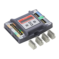
Use Fig. 5 and Tables 1 and 2 to locate the wiring terminals for
the Economizer module.
NOTE: The four terminal blocks are removable. You can slide
out each terminal block, wire it, and then slide it back
into place.
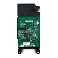
Fig. 5. W7220 Economizer module terminal connection
labels.
1/2 (13)
1. STRIP 1/2 IN. (13 MM)
FROM WIRES TO
BE ATTACHED AT
ONE TERMINAL.
2. TWIST WIRES
TOGETHER WITH
PLIERS (A MINIMUM
OF THREE TURNS).
3. CUT TWISTED END OF WIRES
TO 3/16 IN. (5 MM) BEFORE INSERTING
INTO TERMINAL AND TIGHTENING SCREW.
THEN PULL ON EACH WIRE IN ALL
TERMINALS TO CHECK FOR
GOOD MECHANICAL CONNECTION.
M24382
JADE CONTROLLER
LEFT TERMINAL
BLOCK LABEL
RIGHT TERMINAL
BLOCK LABEL
M32283
Table 1. Economizer Module - Left hand terminal blocks.
Label Type Description
Top Left Terminal Block
MAT
MAT
20k NTC
and
COM
Mixed Air Temperature Sensor
(polarity insensitive connection)
OAT
OAT
20k NTC
and
COM
Outside Air Temperature Sensor
(polarity insensitive connection)
S-BUS
S-BUS
SYLK Bus Sylk Bus sensor
(polarity insensitive connection)
Bottom Left Terminal Block
IAQ COM COM Air Quality Sensor Common
IAQ 2-10 2-10 Vdc Air Quality Sensor Input
(e.g. CO
2
sensor)
IAQ 24V 24 Vac Air Quality Sensor 24 Vac Source
ACT 2-10 2-10 Vdc Damper Actuator Output (2-10 Vdc)
ACT COM COM Damper Actuator Output Common
ACT 24V 24 Vac Damper Actuator 24 Vac Source
Table 2. Economizer Module - Right hand terminal blocks.
Label Type Description
Top Right Terminal Block
n/a The first terminal is not used
SD-O/B 24 Vac IN Shut Down (SD) Conventional only
or
Heat Pump Changeover (O/B)
OCC 24 Vac IN Occupied / Unoccupied Input
E-GND EGND Earth Ground
EXH1 24 Vac OUT Exhaust Fan 1 Output
AUX 24 Vac OUT Programmable:
Exhaust fan 2 output
or
ERV
or
System Alarm output.
Bottom Right Terminal Block
Y2-I 24 Vac IN Y2 in - Cooling Stage 2 Input from
space thermostat
Y2-O 24 Vac OUT Y2 out - Cooling Stage 2 Output to
stage 2 mechanical cooling
Y1-I 24 Vac IN Y1 in - Cooling Stage 1 Input from
space thermostat
Y1-O 24 Vac OUT Y1 out - Cooling Stage 1 Output to
stage 1 mechanical cooling
C COM 24 Vac Common
R 24 Vac 24 Vac Power (Hot)
 Loading...