JADE™ ECONOMIZER MODULE
63-2700—01 6
Sylk Bus Sensor Wiring
Use Fig. 6 and Table 3 to locate the wiring terminals for each
Sylk Bus sensor.
Use Fig. 6 and Table 4 to set the DIP switches for the desired
use of the sensor.
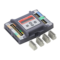
Fig. 6. Sylk Bus sensor DIP switches.
Table 3. SYLK Bus Sensor Wiring Terminations.
Terminal
Type DescriptionNbr Label
1 S-BUS SYLK
Bus
Sylk Bus Communications
(Sensor Bus)
2 S-BUS SYLK
Bus
Sylk Bus Communications
(Sensor Bus)
Table 4. SYLK Bus Sensor DIP Switch Settings.
Use
DIP Switch Positions for Switches 1, 2, & 3
123
DA
a
a
DA = Discharge Air
OFF ON OFF
RA
b
b
RA = Return Air
ON OFF OFF
OA
c
c
OA = Outside Air
OFF OFF OFF
DIP
SWITCH
LABEL
M32271
SYLK BUS
TERMINALS
(1 AND 2)
DIP
SWITCHES
(3)
SYLK BUS
2 PIN “EURO”
CONNECTOR
 Loading...