4-20 mA
Controlled
Current Source
Internal
Power
Loads
J4
INT EXT
J5
EXT INT
11
10
9
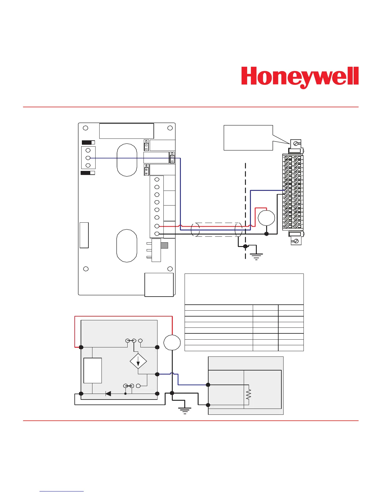
MIDAS
Simplified Internal Schematic
2
1
-
+
System 57
Relay/Field
Interface Card
5704 Control Card
19
17
Sense
Resistor
Cabinet
(NS) 19
(01) 17
Shielded Cable
RJ-45
8
7
2
3
4
5
6
1
DC
PWR
+24 V
COM
NO
NC
Relay3
Relay2
Relay1
ON
SW
OFF
11
10
9
Analog Current
Loop 4-20 mA
INT EXT
EXT INT
-supply
J5
J4
+supply
J1
NO
NC
J2
NO
NC
J3
PYROLYZER
CONNECTOR
Relay1
}
Relay2
}
Relay3
}
Sieger System 57
Quad Relay Interface Card
05704-A-0121
with
4 Channel Control Card
05704-A-0145
+
24
VDC
-
+
24
VDC
-
Note:
The above schematic shows the MIDAS connected
to channel 1 on the 5704 card. The terminal numbers
for all four channels are as follows:
MIDAS Function Analog Out Common
Midas Terminal Number
Color in this figure
5704 Channel 1 Terminal
5704 Channel 4 Terminal
5704 Channel 3 Terminal
5704 Channel 2 Terminal
10
Blue
17
24
23
18
System 57 Function 01
1
Black
19
26
25
20
NS
 Loading...