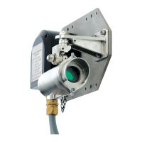
Do you have a question about the Honeywell RAEGuard 3 and is the answer not in the manual?
Outlines specific conditions for safe operation, including alarm behavior and sensor states.
Details Honeywell's warranty policy, coverage, and limitations for the RAEGuard 3.
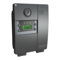
Describes the RAEGuard 3 transmitter's features, display, and user interface.
Explains sensor types for detecting different gases using various technologies.
Lists available standard and optional accessories for enhancing RAEGuard 3 functionality.
Details the optional HART communication for remote configuration and maintenance.
Provides instructions and diagrams for mounting the RAEGuard 3 transmitter.
Guides on how to replace or install toxic, oxygen, flammable, and NDIR sensors.
Describes the procedure for remotely mounting sensor parts using a junction box.
Explains the wiring requirements for 4-20mA source current output and HART function.
Identifies and defines terminal connections for power, signal, communication, and relays.
Specifies power requirements, consumption, and cable specifications for the detector.
Details effective earth/ground bonding for EMC/RFI immunity and connection methods.
Describes the RAEGuard 3's LCD display features and indicators.
Explains how to interpret system status indications via LEDs and LCD messages.
Details the operation of the RAEGuard 3 using the magnetic wand interface.
Outlines the three operating modes: Monitor, Configuration, and View.
Provides procedures for zeroing and span calibration using calibration gas.
Explains how to perform a bump test for gas response check.
Discusses the typical operational life of different sensor types and maintenance recommendations.
Details the procedure for replacing flammable/NDIR and toxic/oxygen sensors.
Guides on replacing internal circuit modules like Display, Main, and Terminal PCBs.
Explains how to browse parameter settings without modification.
Describes accessing basic and advanced configuration menus using passwords.
Provides mechanical drawings for vertical, horizontal, and wall mounting.
Illustrates the wiring diagram for 4-20mA, RS485, and relays.
Shows the drawing for installing the device using a duct mount kit.
Presents the drawing for the collecting cone accessory.
Shows the drawing for the sunshade/deluge protection cover.
Displays the drawing for the mounting plate kit.
Presents the drawing for the gas flow adapter.
Details the nameplate information for the RAEGuard 3 LEL model.
Details the nameplate information for the RAEGuard 3 EC model.
Details the nameplate information for the RAEGuard 3 NDIR model.
Details the nameplate information for the 7R i-sensor LEL.
Details the nameplate information for the 7R i-sensor NDIR.
Details the nameplate information for the 7R i-sensor EC.
Shows the relative cross sensitivity of RAEGuard 3 sensors to other gases.
Explains calibrating flammable gas detectors using correction factors.
| Target Gas | Oxygen, Combustible gases, Toxic gases |
|---|---|
| Detection Principle | Electrochemical, Catalytic, Infrared |
| Sensor Type | Electrochemical, Catalytic Bead |
| Display | LCD |
| Operating Temperature | -20°C to 50°C |
| Operating Humidity | 0% to 95% RH |
| Power Supply | Rechargeable lithium-ion battery |
| Output | 4-20 mA, Relay |
| Communication | HART |
| Certifications | UL, ATEX, IECEx |
| Detection Range | 0-100% LEL for combustible gases, specific ranges for other gases |

