RAEGuard 3 User Manual
21
5.3 Power
Note:RAEGuard 3 series detector is designed for use in potentially explosive
atmosphere and hazardous environments. The installation of detectors should
ensure their explosion-proof performance and strictly comply with the relevant
national standards, to use industrial-grade armored cables and explosion-proof
glands and conduits.
All unused and used cable/conduit entries must be sealed with a suitable certified
sealing plug and cable gland.
Use 0.5mm
2
(20AWG) to 2.5mm
2
(13AWG) cross sectional area cable as needed
to ensure minimum operating voltage at the detector, depending on installed cable
length.
Maximum Cable Length (km)
The above data is based on the normal supply voltage of 24VDC.
RAEGuard 3 supports RS485 Modbus RTU protocol. It is recommended to use
shielded twisted-pair cable to communicate with the master system. The
maximum communication distance is as follows:
5.4 Cable and Earth/Ground regimes
Effective Earth/Ground bonding is important to ensure good EMC and RFI
immunity.
The Earth Screen of the field cable should be “tied to Earth” or connected to
Ground at one point only. It is common practice to adopt a STAR EARTH
connection regime where all instrumentation screens are connected at one
common point.
The Screen at the other end of the cable should be “parked” or terminated into
a blank terminal.
External Ground Connection
As shown in below figure, one end of the grounding wire is tightened to the
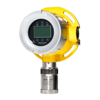
 Loading...

