

D
Daniel KrauseJul 27, 2025
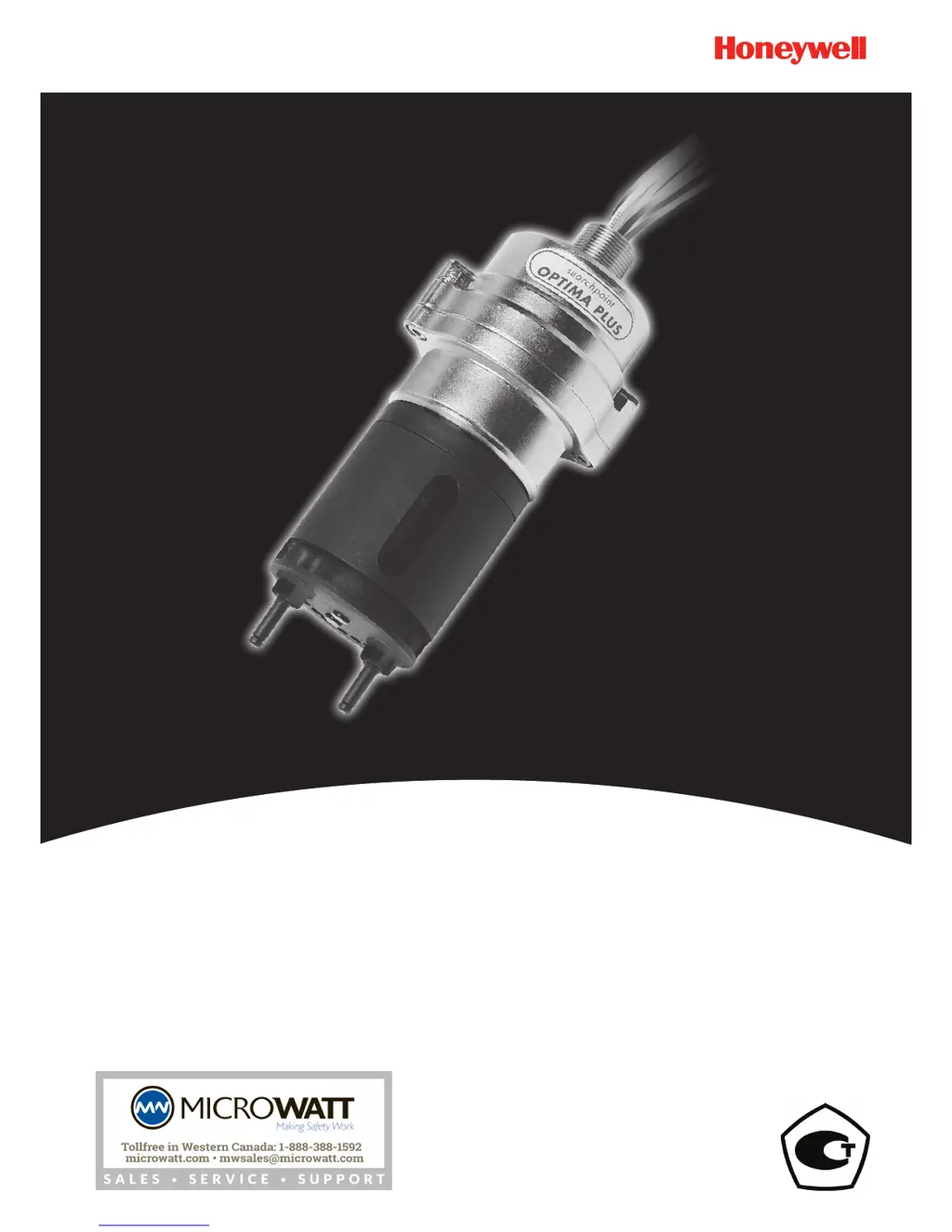
What to do if Honeywell Searchpoint Optima Plus Gas Detectors shows a warning for a bad 4-20mA loop?
- WwolfstevenJul 27, 2025
If your Honeywell Gas Detectors unit shows a warning of a bad 4-20mA loop, which can latch the 4-20 mA output, it could be due to an error greater than ±0.5 mA in the analogue output. If this occurred while connecting/disconnecting a multimeter, re-cycle the power or reset to clear the latch. Also, inspect the 4-20 mA loop connections and cabling, and ensure the loop resistance is less than 600 ?. If the supply voltage is between 18 to 20 Vdc in current source mode, the maximum loop resistance is 500 ?.