28
5. In order to reduce the likelihood of radio frequency interference affecting the operation of units it is
recommended that neither units nor their cabling are installed in close proximity to the antennae of high
powered radio, radar or satellite communication equipment.
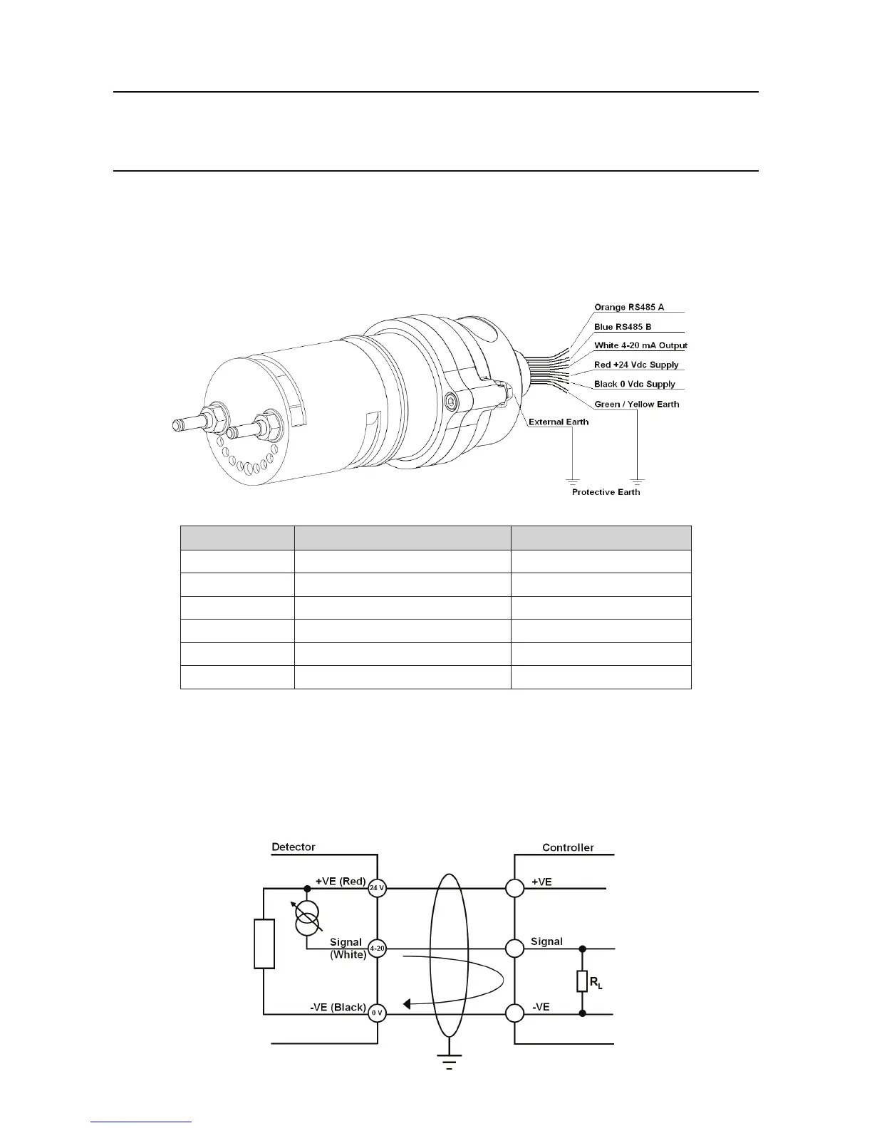
4.4 Connections
Wire Colour Connection Purpose
Red +24 Vdc +ve Supply
Black 0 Vdc -ve Supply
White 4-20 mA Output Signal
Orange RS485 A SHC1 Communication
Blue RS485 B SHC1 Communication
Green/Yellow Earth Protective Earth
Note:SearchpointOptimaPlusisreversepolarityprotected.
The connection diagrams below show Searchpoint Optima Plus connected in current sink or current source
mode.
Note:SearchpointOptimaPluswillautomaticallydetectwhetheritshouldoperateincurrentsinkorcurrent
source mode.
Searchpoint Optima Plus Current Source Connection
4. Electrical Installation

 Loading...