RAEGuard 3 User Manual
19
4.1 Transmitter wiring
Note: All electrical connections should be made in accordance with any
relevant local or national legislation, standards or codes of practice.
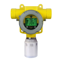
RAEGuard 3 transmitter only supports source current output with 3 wires 4-20mA.
Please refer to the wiring diagram as below.
Note: Terminate cable screen at detector or controller (that is maybe gas controller,
also be upper system), not both.
250ohm load resistor (RL) is installed in the factory, in case of connection with
controller, this resistor should be removed because controller has load resistor
internally.
If you choose a RAEGuard 3 transmitter that supports HART function.
Communicate to the HART terminal, please refer to the following connection
diagram.
Host

 Loading...

