8 Installation Instructions MB-Secure 1000/2000/3000/4000/5000/6000
2 Control panel design
The MB-Secure PCBs are compatible for installation in the following control panel housings:
MB-Secure original control panel housing: 013730, 013740, 013750, 013760
Replacement of MB-Classic PCBs: 012911, 013201.10, 013202.10, 013106, 013203.10,
013204.10, 013222.10, 013223.10
Use in other housings is not recommended because the fixing points differ and correct grounding
cannot be guaranteed.
If the energy supply of the intrusion alarm control panel is not an integrated part of it, then it has to be
installed directly adjacent to the intrusion alarm control panel (without space in between). It should not
be possible to tamper with the connecting cables without causing mechanical damage to the housing.
VdS guidelines 2311
Starting from approximately the first quarter of 2016 the doors of housings ZG 2 (item no. 013740) and
ZG 3.1 (item no. 013750) will be supplied with an opening for installing a lock insert. An individually
keyed lock insert (part. no. 028051) should be used for VdS-compliant installations.
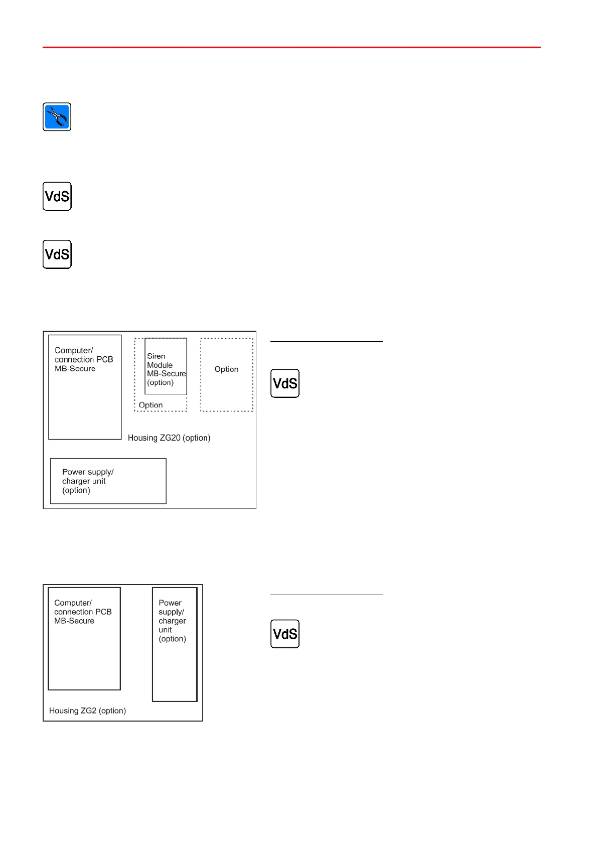
2.1 Control panel in the ZG 20
Emergency power supply
The housing provides space for 1 battery with max. 18 Ah.
According to VdS guidelines the batteries are to
be secured using a fixing strap (055280). Please
refer to chapter 3.4 Installing power supply unit
and battery in housing ZG20.
2.2 Control panel in the ZG 2
Emergency power supply
The housing provides space for 2 batteries with max. 6.5 Ah.
According to VdS guidelines the batteries are to
be secured using a fixing strap (055280).
 Loading...


