43-TV-33-56 iss.4 GLO Aug 19 UK 14
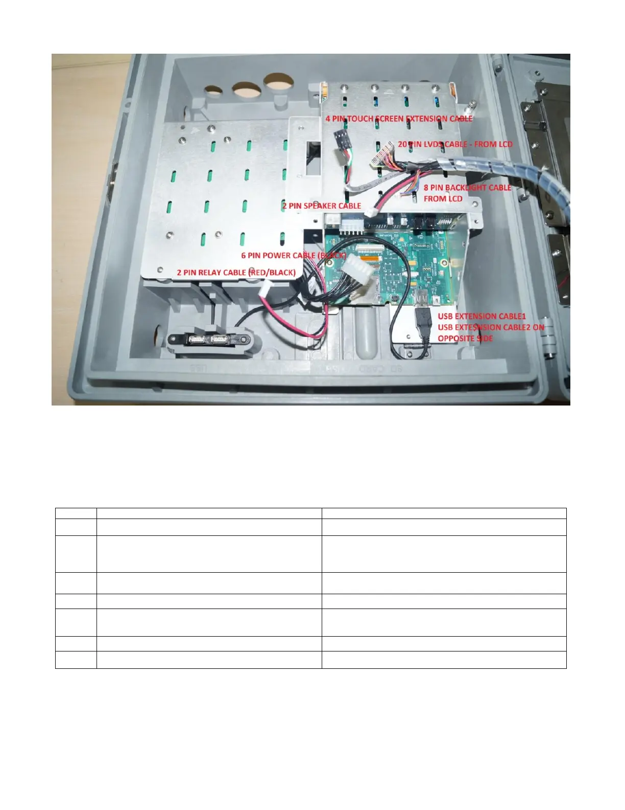
Figure 25 - Cables to be connected inside slant chassis plate to the CPU board
3. Lift the IO card chassis; fold back the bottom stand inside and keep the IO card chassis back into the case for
reconnecting the different cables.
Connectors of all the cables are polarized; make sure to connect the connectors as per notch direction. The table
below shows the different cables used and where they should be connected.
Relay extension cable – for status of power relay
Power supply Board to Backplane board (J10)
Touch Screen Extension Cable – for extending the
touch screen connections from the touch screen to
the CPU board
Touch screen in Bezel to CPU board in case (J5 – Notch
on cable should face EXT SD connector – J8)
Backlight Cable – For backlight driver board
Backlight driver board to backlight connector on the CPU
board (J14)
LVDS Cable – For LCD data
From LCD in bezel to CPU board (J11)
Speaker cable – For extending the speaker
connections
Speaker to speaker connector on the TVDRG2
backplane board (J6)
Earth Braid – For strong ground connection
From LCD bracket to the IO cards chassis
Power Supply Board to Backplane Board (J10)

 Loading...