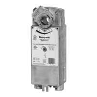
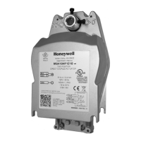
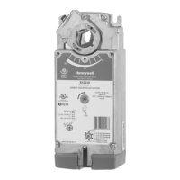
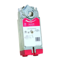
3 NM, 5 NM SERIES SPRING RETURN DIRECT COUPLED ACTUATORS
62-0274—07 6
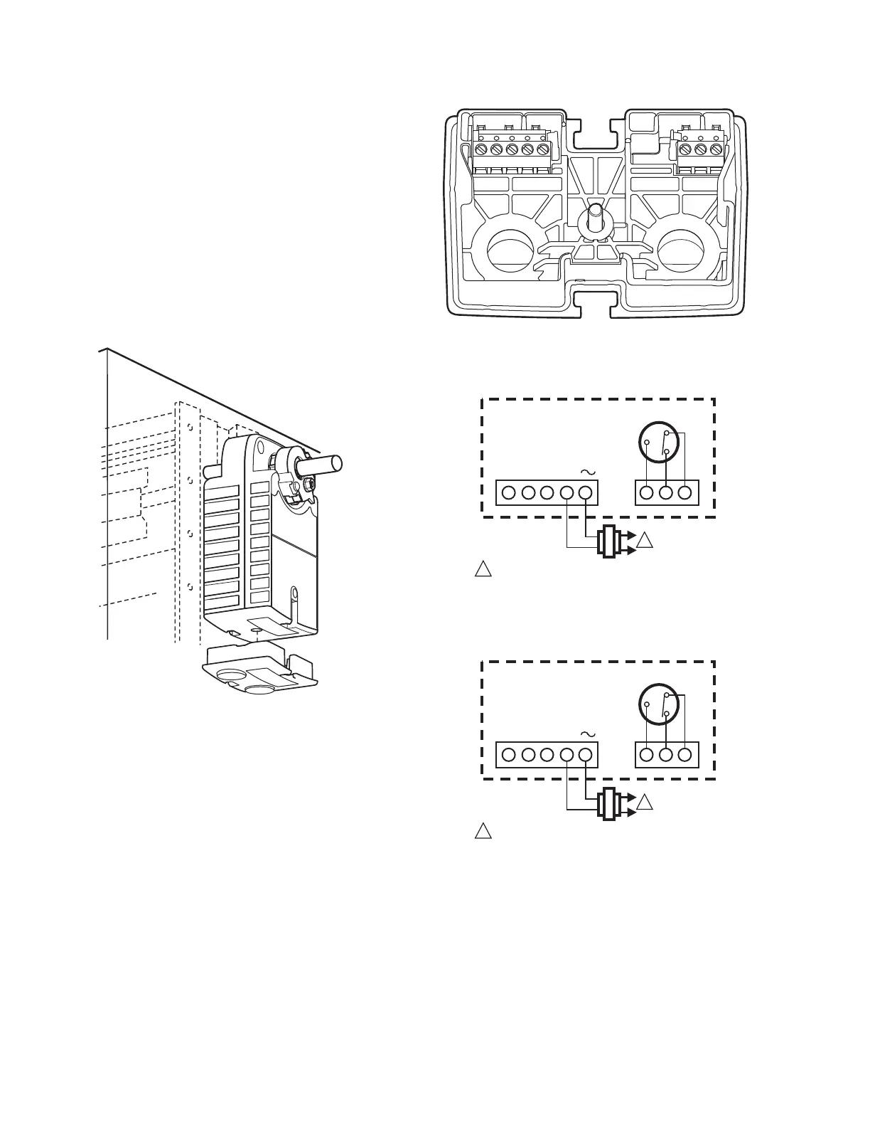
NOTE: This cover can be removed before or after mounting
actuator to the damper shaft or valve linkage.
In order to wire the device, the access cover must be removed
as follows:
1. Remove the screw from the center of the cover, set the
screw aside.
2. Pull the cover along the long axis of the actuator.
3. If the actuator is not yet mounted, set it aside.
4. Remove conduit dust covers.
5. Thread wire through conduit holes.
6. Connect wires as appropriate to the terminal block(s).
(See Fig. 9 and 11.)
NOTE: Use either 1/2 in. x 14 NPS or M20 x 1.5 strain
relief or conduit adapters.
Fig. 8. Removing access cover.
Typical Wiring Without Cables
See Fig. 9 through 23 for typical wiring details for actuators
without cables (whips). See Fig. 24 through 26 for wiring
actuators with cables (whips).
Fig. 9. Terminal block details.
Fig. 10. Terminal block details.
Fig. 11. S-BUS Terminal block details.
90° -0°
OR
N/A
90° -0°
OR
+
1 POWER SUPPLY. PROVIDE DISCONNECT MEANS AND
OVERLOAD PROTECTION AS REQUIRED.
S3 S2
S1
FEEDBACK
ACTUATOR
1
5
3
1
2
M32677
4
T
S-BUS
1 POWER SUPPLY. PROVIDE DISCONNECT MEANS AND
OVERLOAD PROTECTION AS REQUIRED.
S3 S2
S1
ANALOG OUTPUT
ACTUATOR
1
5
3
1
2
M32677
4
T
S-BUS
 Loading...