VRN PRESSURE INDEPENDENT CONTROL VALVES AND ACTUATORS
38-00032—01 18
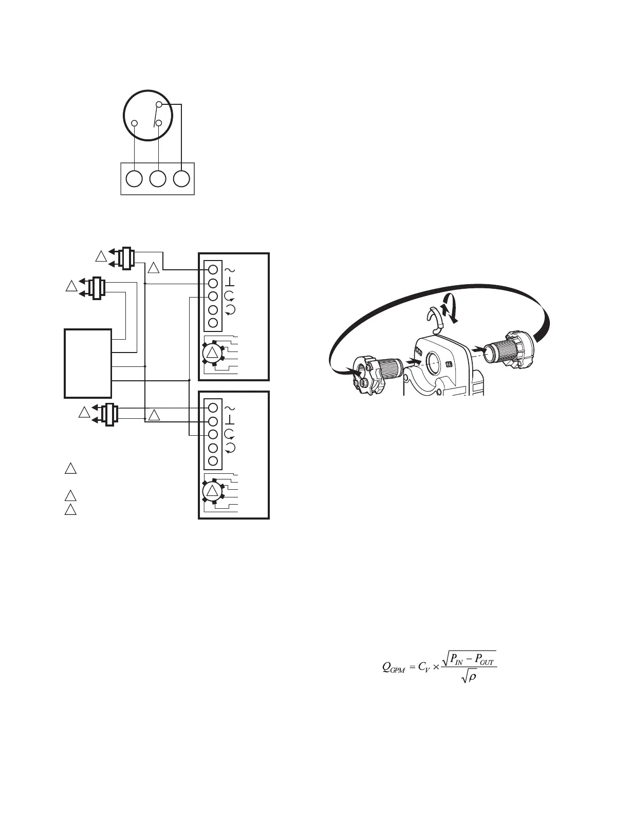
Fig. 26. Wiring for model with aux./end switches.
Fig. 27. MS7505 with Proportioning controllers
operating multiple actuators (Modulating mode setting).
NOTE: All identified parts except for the valve body and
aluminum valve stem coupler are included in
Replacement Kit (part no. 5112-11).
OPERATION AND CHECKOUT
Once both the mechanical and electrical installations are
complete:
1. Cycle the actuator to verify that the direction of rota-
tion suits the control sequence.
2. If the rotation direction is incorrect:
a. For 2-position spring return actuators: Remove,
flip over, and replace actuator on the bracket.
b. For floating control actuators: Reverse two control
signal wires (CW/CCW), or change position of
selector switch.
c. For analog control actuators either:
(3) Change setting of reverse/direct-acting
switch, or
(4) Remount actuator on the bracket.
3. If the control scheme requires fail-safe operation,
ensure that, upon removal of power, the fail position
coincides with the control sequence.
4. Spring return actuators are factory-configured for
normally-closed, fail-safe operation on power loss. To
change this action to normally-open, remove and
reinstall the actuator in the opposite orientation as
follows:
a. Loosen the shaft coupling bolt using a 10 mm
wrench.
b. Loosen all other mounting bolts connecting the
actuator to the mounting bracket, and set aside.
c. Remove the actuator from the valve shaft.
d. Move the Self-Centering Shaft Adaptor to the
opposite side of the actuator, as displayed in
Fig. 28.
Fig. 28. Change actuator to normally open.
(1) Remove the retainer clip from the
Self-Centering Shaft Adapter and set it aside
for later use.
(2) Remove SCSA from actuator.
(3) Reinstall SCSA on the opposite side of the
actuator, aligning it based on the stroke
labeling.
(4) Replace the retainer clip on the shaft coupling
using the groove of the coupling.
e. Reconnect the actuator to the valve mounting
bracket by replacing the screws previously
removed (step b).
f. Tighten the shaft coupling bolt using a 10 mm
wrench or socket.
Operation
The differential pressure regulator maintains constant
pressure drop across the valve seat through a wide range of
head pressures. At a given ball position, flow through the
valve will be constant as defined by the formula:
where ρ is the density of the glycol mix.
P
IN
changes constantly in a multi-zone system as other
valves open and close, changing system flow and head
pressure according to the characteristics of the supply
pump curve. Reaction of the mechanical pressure
regulator is instantaneous, eliminating changes in room
ACTUATOR
0/2 TO 10 VDC
PROPORTIONING
CONTROLLER
1
2
3
2
LINE VOLTAGE POWER SUPPLY.
PROVIDE DISCONNECT MEANS AND
OVERLOAD PROTECTION AS REQUIRED.
24 VDC SUPPLY ACCEPTABLE.
SET SWITCH TO MODULATING.
V
OR +
OR N/A
FEEDBACK
5
4
3
1
2
M34978
2-10 VDC
10-2 VDC
0-10 VDC
10-0 VDC
Fltg, fwd
Fltg, rev
3
ACTUATOR
V
OR +
OR N/A
FEEDBACK
5
4
3
1
2
2-10 VDC
10-2 VDC
0-10 VDC
10-0 VDC
Fltg, fwd
Fltg, rev
3
24 VAC
1
24 VAC
1
2
24 VAC
1
HOT
COM
–
+
M27714
 Loading...