ECN12-0027 3
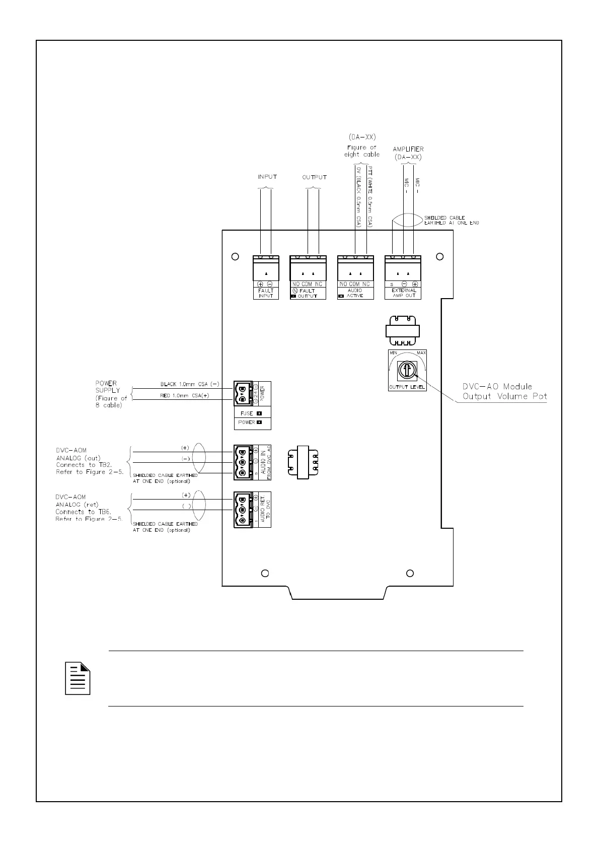
5. Using Figure 2-4, Figure 2-5 and Figure 2-6 as a reference wire the;
a. MIC+, MIC- cable from the Amplifier to the DVC-AO Interface Module
b. 0V and PTT cable from the Amplifier to the DVC-AO Interface Module
c. Power Cables from the power supply to the DVC-AO Interface Module
d. Audio In cables from the DVC-AO Analog board to the DVC-AO Interface Module
e. Audio Rtn. cables from the DVC-Analog board to the DVC-AO Interface Module
Figure 2-4 - DVC-AO Interface Module Connection Diagram
NOTE: The Fault Input is shorted in Normal Operation. The fault Input indicates a fault when
the input becomes an open circuit.
 Loading...


