PRO-2200 Remote Enclosure—PRO22ENC3 11Installation Guide
Installation Instructions
1. Remove the 16.5 V 20 VA wall transformer from the enclosure.
2. Measure and install the top two mounting screws with heads smaller than .4" (0,1016
m) using proper mounting techniques for the material being used to hold the
PRO22ENC3. Space the screws 13.75" (0,349 m) apart. Leave the screws exposed
approximately 1/2" (1.27 mm).
3. Open the door of the enclosure and place the hanging slots over the mounting screws.
Push the enclosure over the mounting screws and allow the screws to slide into the
slots. Finish tightening the mounting screws to securely hold the enclosure. Screw in
the lower hanger to secure the enclosure against the wall.
4. Run all appropriate wiring to the case through metal conduit. Mark each wire as to
the panel, location and input type. All cable shields should tie to the copper grounding
stud found on the bottom left of the enclosure.
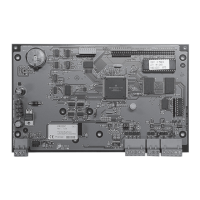
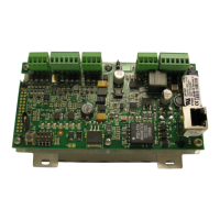
5. Install the required panels onto the proper standoffs using the supplied screws. When
using two full size panels make sure the unused standoffs have nylon screws in
them to prevent short circuits on the panels. This enclosure can mount two full
size PRO-2200 panels OR one full size panel, one PRO22R1 single reader panel and
one PRO22MX8 multiplexer panel.
6. Wire the readers, input and output connections (see wiring guide at end of booklet).
7. Check all connections prior to powering up the enclosure and panels.
8. Wire the power supply through the wall transformer provided. Connect to the AC
terminals. Check the voltage at DC+ and DC-. The voltage should be approximately
13.8 VDC.
9. Disconnect the power.
10. Connect the DC power to the panels in parallel. Insure that the connection has the
correct polarity. Follow the wiring diagram supplied with the panels.
11. Wire the AC FAIL and LOW BATT normally closed to appropriate inputs on the panels.
See individual panel wiring diagrams supplied with the panels.
12. Connect the green and yellow Tamper Switch wires to the appropriate inputs on the
panels. See individual panel wiring diagrams supplied with the panels.
13. Connect Communications wiring per the wiring diagram supplied with the panels.
14. Attach the red battery charging connection to the positive terminal of the battery. The
negative connection is connected at the factory.
15. Check all connections prior to powering up the enclosure and panels.
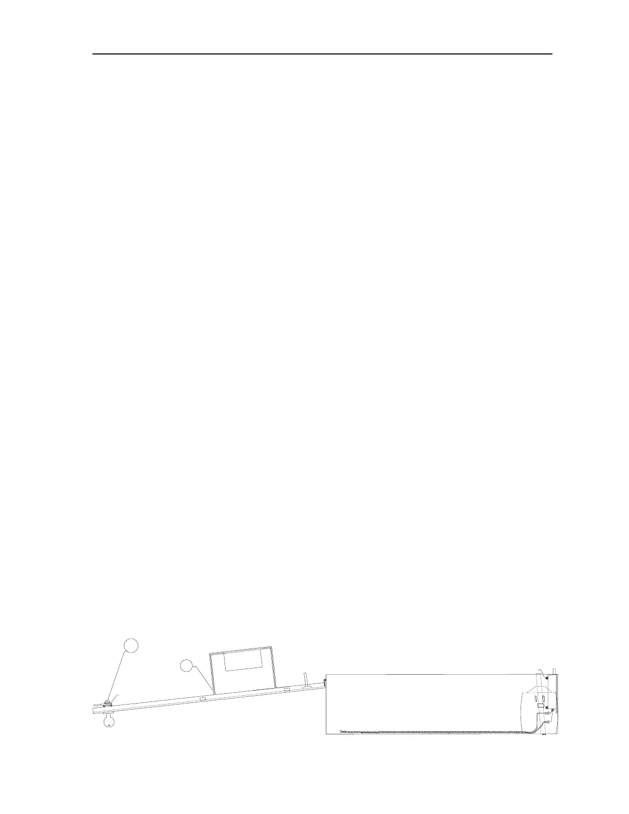
Installation Diagram 1
W/KEY INSTALLED
SHOWN IN
LOCKED POSITION
SIDE VIEW
15
LOCK
BRACKET
1-REQ'D
12
 Loading...