12 PRO-2200 Remote Enclosure—PRO22ENC3Installation Guide
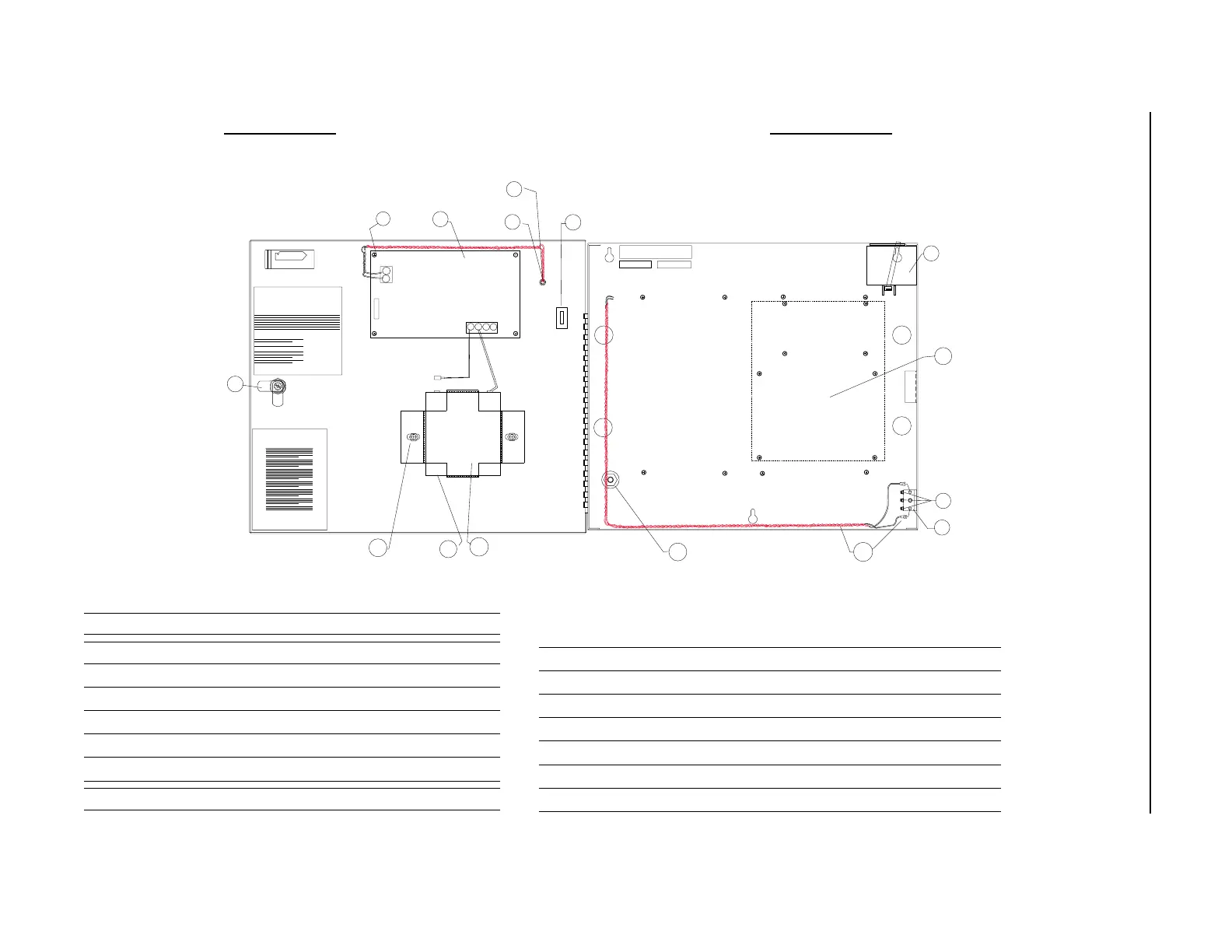
Installation Diagram 2
Left Open View Right Open View
Part Description
1 Screw 6–32 x 1/4" 12
2 12 VDC Power Supply 1
3 Power Indicator Light Assembly 1
4 Retaining Ring 1
5 Kurly Lok 1
6 16.4 VAC 20 VA Wall Transformer 1
7 Nylon Screws 6–32 x 3/16"
8 KEPS Nuts 6–32 3
9 Tamper Switch 1
10 Tamper Switch Wire Assembly 1
11 Nuts 8–32 2
12 12 V Battery Bracket 1
13 12 V 4.0 amp hour Sealed Battery 1
14 Nut 1/4"–20 Hex with Nylon Insert 2
15 Lock with Key 1
TAMPER
SWITCH
1-REQ'D
NUT 6-32 KEPS
3-REQ'D
YEL
GRN
FIRE SAFETY NOTICES ...
Notices
FCC-CDOC and
Fire Safety...
PLACE
STICKER
1/8" FROM
EACH EDGE
BRACKET
1-REQ'D
LOCK W/SF1400
1-REQ'D
BATTERY
1-REQ'D
12
13
8
9
10
15
ADD 2 TO STUD
TAMPER SWITCH
WIRE SET
POWER IND LIGHT
WIRE ASSEMBLY
1-REQ'D
RETAINING
RING
1-REQ'D
3
4
14
AC
AC
AC FAIL
NO
NC
NO
NC
LOW BAT
+BAT- +DC-
PLACE NYLON
SCREWS INTO
THESE 8 STANDOFFS
SN/1234
date
code
PRO22ENC3
WALL
TRANSFORMER
1 REQ'D (X-5)
6
7
2
1
CONNECT POSITIVE
TAB ON BATTERY
4 REQ'D
5
KURLY
LOK
11
PRO22E3PS
BAT-3
**IMPORTANT**
SUPPRESSORS MUST BE USED
WITH STRIKES, NORTHERN S-4
**IMPORTANT**
ENCLOSURE MUST BE
EARTH GROUNDED
 Loading...