Do you have a question about the Honeywell PW6K1ICE and is the answer not in the manual?
Provides decision making, event reporting, and database storage for the Honeywell hardware platform.
Details UL-compliant installation requirements for the PW6K1ICE panel, including area, indoor use, and tamper switch.
Describes control of one physical barrier using single or paired readers, inputs, relays, and LEDs.
Outlines access control features: cardholder capacity, transaction buffer, access levels, PINs, and activation dates.
Details supported card formats, including PIV-II, CAC, TWIC, and anti-passback support.
Lists compatible card readers from HID and Honeywell, including models and part numbers.
Covers alarm management, including normally open/closed, supervised/unsupervised circuits, and EOL resistances.
States Honeywell Security Access warranty for defects in material and workmanship for one year.
Disclaims liability for life-critical applications, misapplication, or malfunction of the product.
States compliance with FCC Rules Part 15, regarding interference and operation.
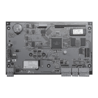
Details the PW6K1ICE control board, including dimensions, tamper switch, reset, DIP switches, and status LEDs.
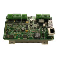
Provides a comprehensive table of terminal connections for inputs, outputs, power, and relays on the PW6K1ICE.
Explains jumper settings (J1-J7) on the PW6K1ICE board, including PoE, 12VDC power, and Ethernet connection.
Details the function of the four DIP switches (S1) for configuring operating modes and processor reset.
Lists default communication parameters like IP address, communication address, and host port.
Describes the procedure to erase all configuration and cardholder databases using DIP switches.
Explains the two methods for powering the PW6K1ICE: PoE and local 12VDC supply.
Details communication wiring via the on-board 10-BaseT/100Base-TX Ethernet port.
Covers wiring for the two reader ports, supporting Wiegand, magnetic stripe, and RS-485 interfaces.
Explains wiring for input circuits monitoring door position, exit requests, or alarm contacts, including supervised/unsupervised configurations.
Describes wiring for the two relays used for door lock mechanisms or alarm signaling, including contact types and protection.
Details the SRAM backup battery, its data retention period, and consequences of corruption.
Explains the meaning of status LEDs during power-up, initialization, and running states.
Provides detailed technical specifications for power input/output, SRAM battery, host communication, inputs, relays, and cable requirements.
Offers additional mounting details including dimensions, weight, enclosure requirements, and tamper switch installation.
Introduces the PW6K1ICE's built-in web server (ACDSM) for network and system configuration.
Guides through the initial connection process to ACDSM, including IP addresses and DIP switch settings.
Explains how to log in to the Configuration Manager using default or configured user credentials.
Addresses security certificate issues, including warning messages and the process for handling invalid certificates.
Covers the configuration of the web server, including network, host, device info, and user settings.
Describes the Home screen of the Configuration Manager, showing the navigation bar for accessing various settings.
Details how to configure IP address, hostname, subnet mask, gateway, and DNS server settings.
Explains how to configure primary and alternate host port settings, including connection type, data security, and IP addresses.
Allows viewing of read-only device information, including product ID, hardware revision, serial number, firmware, and IP address.
Covers user management, including setting password strength criteria and adding/editing/deleting users.
Explains the Auto Save feature for restoring or clearing settings, and setting save delay times.
Describes how to restore default factory or current operational settings for network and host communication.
Guides on loading certificate files (.crt) and private key files (.pem) for secure communication.
Details the process of initializing the system and performing a software download after panel creation.
Instructions on how to log out of the web server configuration to complete the process.
| Model | PW6K1ICE |
|---|---|
| Category | Controller |
| Type | Intelligent Controller |
| Output Type | Relay |
| Contact Rating | 2A @ 30 VDC |