10 www.honeywell.com
PW6K1ICE Wiring and Setup
Jumper Configuration
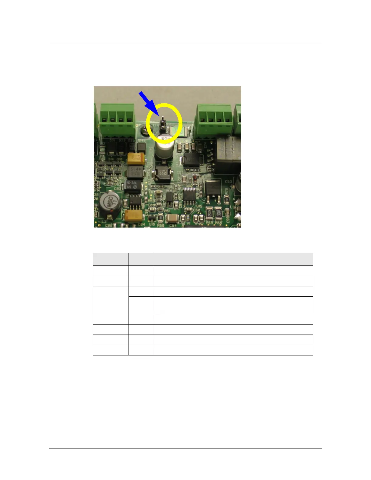
2.3 Jumper Configuration
Figure 2-3: J3 Jumper Location
Table 2-2: Jumper Settings
Jumper Set at Description
J1 N/A Factory Use Only
J2 N/A Factory Use Only (A, B, and C pads)
J3 PoE PW6K1ICE powered from the Ethernet connection
12V PW6K1ICE powered from an external 12VDC power source
connected to TB4-3 (VIN), TB4-4 (GND)
J4 N/A Factory Use Only
J5 N/A Factory Use Only
J6 N/A 10Base-T/100Base-Tx Ethernet Connection (Port 0)
J7 Cabinet Tamper: normally open switch
 Loading...