12 of 12
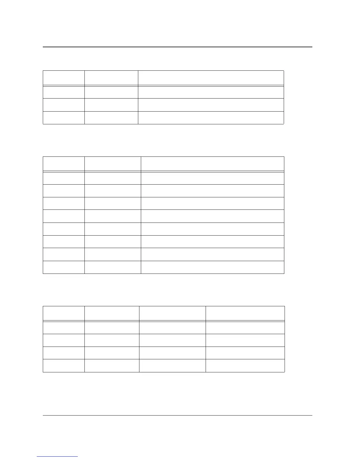
Connector Layout and Cabling Information
Document 800-08279, Revision A
February 2011
© Honeywell International. All rights reserved.
Pin No Pin Assignment Wire Color
1AC NeutralBlack
2 No Connect N/A
3 AC Line/Live White
Table 1: Cable Assembly AC Power Inlet and LED Power Indicator Connections, CN1
Pin No Pin Assignment Wire Color
1 -V Black
2 No Connect -
3+V Red
4 No Connect -
5 Bat + Red (Fast On Connector)
6 No Connect -
7 Bat - Black (Fast On Connector)
8 No Connect -
Table 2: Cable Assembly 12VDC Power and Battery Connections, CN2
Pin No Pin Assignment Wire Color Contact State
1 AC Fail White Open AC OK
2 AC Fail Black Open AC OK
3 Battery Fail Black Open Batt OK
4 Battery Fail White Open Batt OK
Table 3: Cable Assembly AC and Battery Fail Connections, CN3
 Loading...