EasyManua.ls Logo

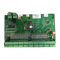
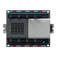
Honeywell PW6K1IN - Wiring Diagram for Connectors 1 through 12

Honeywell PW6K1IN
21 pages
To Next Page IconTo Next Page
To Previous Page IconTo Previous Page
Loading...
10 www.honeywell.com
Installing the PW-6000 Input Module
Wiring Diagram for Connectors 1 through 12
Figure 1: PW-6000 Input Module Wiring: Connectors 1-12
Note: See LED Operation on page 5 for descriptions of LEDs D1-D22.
DIP SWITCHES
INPUT BOARD
Short
together*
Power
RS-485
NO
C
CardRack PWR
and
Com Harness*
(Rack Mount
Only)
EOL
EOL
Alarm
Input
Sensor
Input
RS-485 TR+
RS-485 TR-
RS-485 GND
+ 12V
GND
IN14
IN14 Common
IN15
IN15 Common
IN12
IN12 Common
IN13
IN13 Common
IN10
IN10 Common
IN11
IN11 Common
IN8
IN8 Common
IN9
IN9 Common
IN6
IN6 Common
IN7
IN7 Common
IN4
IN4 Common
IN5
IN5 Common
IN2
IN2 Common
IN3
IN3 Common
IN0
IN0 Common
IN1
IN1 Common
Relay 0 NO
Relay 0 C
Relay 0 NC
Self-Powered
Audio / Visual
Alarm Indicator
K 1
K 2
J 1 - RS-485
Termination
J 2
{
1
2
3
1
2
3
1
2
3
4
1
2
3
4
1
2
3
4
1
2
3
4
1
2
3
4
1
2
3
4
1
2
3
4
1
2
3
4
1
2
3
4
5
1
2
3
D1
D2
D3
D4
D5
D6
D7
D8
D9
D10
D11
D12
D13
D14
D15
D16
D17
D18
D19
D20
D21
D22

Related product manuals