Applicator Interface Kit Installation Guide 9
Applicator Interface OUT Signals
The Applicator Interface supports 8 digital output port with optocoupler. There
are two methods to connect the output ports on the 44 pins D-Sub connector of
the Applicator Interface card, Active High or Active Low.
The recommended/default connection is Active Low, in accordance with
this user guide’s logic (Assert = LOW, De-assert = HIGH).
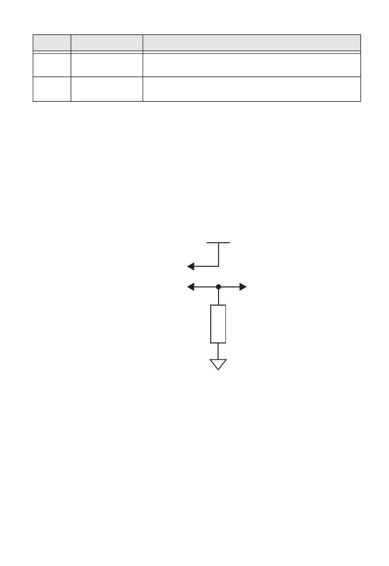
Active Low (Recommended)
Output level is V+ when de-asserted, Output level is V- when asserted.
Active High
Output level is V+ when asserted, Output level is V- when de-asserted.
30 RTWINEXT_K External input signal for Ready-to-work indicator
Anode Opto In Channel
15 RTWINEXT_A External input signal for Ready-to-work indicator
Cathode Opto In Channel
Pin Signal Description
Collector Pins:
6, 8, 20, 22, 24, 35, 37, 39
Emitter Pins:
5, 7, 9, 21, 23, 25, 36, 38
V+
R
 Loading...