KNA Burner Manual 9.801-300.0 rev. 8/13
11
Section: Wiring the Burner
Wiring Connections Diagram
WARNING
Explosion, Fire, Scald and
Burn Hazard
All heating equipment must
have HIGH LIMIT protection to
interrupt electrical power and
shutdown the burner if operat-
ing or safety controls fail and
cause a runaway condition.
• Follow the equipment manufacturer's wiring dia-
grams and note all required safety controls.
• Typical safety controls include high temperature or
pressure limits, low water cutoffs, pressure relief
valves and blocked flue sensing switches.
• Verify all limit and safety controls are installed and
functioning correctly, as specified by the manufac-
turer, applicable safety standards, codes and all
authorities having jurisdiction.
• Ensure that the equipment is free of oil and oil
vapor before starting or resetting the burner.
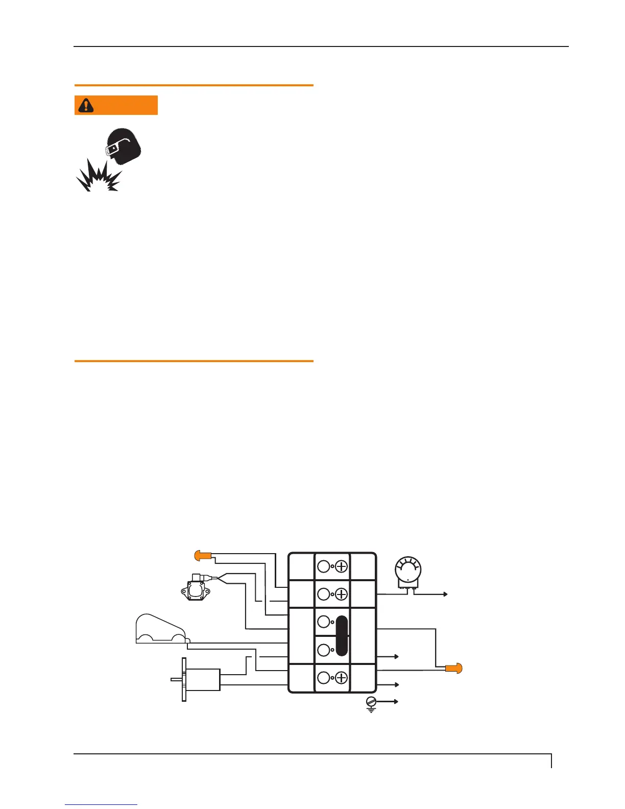
Typical connections to the burner control terminal are
shown in Figures 7a-7f.
Refer to the equipment manufacturer's wiring diagram
prior to connecting the burner wiring. All wiring must be
in accordance with the latest revision of National Elec-
tric Code NFPA 70 and all local codes and regulations.
FIGURE 7a
115V WIRING DIAGRAM WITH 115V SOLENOID COIL
P1 12
THERMOSTAT
POWER
LIGHT
115V
LINE 2
LINE 1
GND
115V
FUEL
SOLENOID
115V
IGNITOR
115V
MOTOR
115V
1
2
3
4
5
SP
FUEL
SOL
L 2
L 1
SP
T-
STAT
L 2
L 1
98013000-1

 Loading...