RLV4300 69-1918EF 7/24/06 1/4
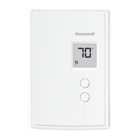
The RLV4300 thermostat can be used to control an electric heating
system such as a baseboard heater, a radiant floor, a radiant ceiling,
a convector, a fan-forced heater, etc. The thermostat cannot be used
with the following:
• a resistive load under 2 A
• a resistive load over 12.5 A
• systems driven by a contactor or a relay (inductive load)
• central heating systems
SUPPLIED PARTS
• One (1) thermostat
• Two (2) 6-32 mounting screws
• Two (2) solderless connectors
TURN OFF POWER TO THE HEATING SYSTEM AT THE MAIN
POWER PANEL TO AVOID ELECTRICAL SHOCK.
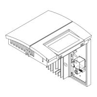
Loosen the screw under-
neath the thermostat and
separate the front plate
from the back plate.
NOTE: The screw cannot
be completely removed.
Connect the thermostat wires to the power and to the load using
solderless connectors for copper wires. The thermostat wires are not
polarized; meaning either wire can be connected to the load or to the
power supply.
NOTE: All cables and connections must comply with local electrical
codes. This thermostat has tinned copper wires for line and load connec-
tions. Special CO/ALR solderless connectors must be used if these wires
will be connected to aluminium conductors.
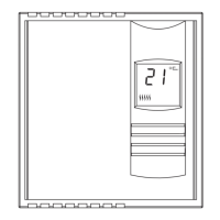
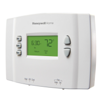
RLV4300
User Guide
5-2 Programmable Thermostat
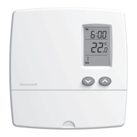
Period no. in
automatic mode
Temperature *
Heating power
indicator
Time and day
Manual
mode
Automatic
mode
Economy
mode
Period no. in
economy mode
Appears if the
thermostat is configured
for a fan-forced heater
Appears during
a power failure
Appears when the
setpoint is displayed
Flashes when the
clock has been reset
Display
* The thermostat normally displays the actual (measured) temperature.
To view the set temperature (setpoint), press either of the buttons once.
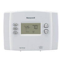
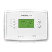
Up/Down buttons
Mode button
Day button
Hour button
Program button
Return button
Screen
Minute button
Pull cover down
n
Description
1.
o
Installation
2.
4-wire Installation
2-wire Installation