SEQUENCE TIMING FOR NORMAL OPERATION
Post Firing Energy Approval
Flame Establishing Period Purge Interlock Rate Saving Code
Device Initiate Standby Purge Pilot Main Run Timing Circuits Circuit Prepurge Bodies
RM7800E 10 sec. * ** 4 or 10 sec. 10 or 15 sec. * 15 sec. Preignition, 4-wire Yes FM/IRI
Lockout, modulating Modulating
High and
Low Fire
RM7800G 10 sec. * ** 4 or 10 sec. 10, 15 sec. or * 15 sec. Preignition, No UL/CSA
Intermittent Running, Modulating
Low Fire
RM7800L 10 sec. * ** 4 or10 sec. 10 or 15 sec. * 15 sec. Preignition, No FM/IRI
Lockout, Modulating
High and
Low Fire
RM7800M 10 sec. * ** 4 or 10 sec. 10 sec. or * 15 sec. Preignition, 2-wire No UL/CSA
Intermittent Running, isoltated On/Off
Low Fire On-Off-On
contacts
* STANDBY and RUN can be an infinite time period.
** PURGE will be determined by which ST7800A purge card is selected.
1
The MFEP will be determined by which terminal is used, configuration jumper selected or jumper wire added, see
Figs. 8, 9, 10, 11 and 30.
RM7800E,G,L,M
SPECIFICATIONS
4
MOUNTING: Q7800A for panel mount or Q7800B for wall
or burner mount.
REQUIRED COMPONENTS:
Plug-in Flame Signal Amplifier, see Table 2.
Plug-in Purge Timer Cards: selectable ST7800A: two
seconds to 30 minutes.
Q7800A or Q7800B.
APPROVAL BODIES:
Underwriters Laboratories Inc. listed, File No. MP268,
Guide No. MCCZ.
Canadian Standards Association certified, LR9S329-3.
Factory Mutual approved, Report No. JI1V9A0.AF.
IRI acceptable.
Federal Communications Commission, Part 15, Class B—
Emissions.
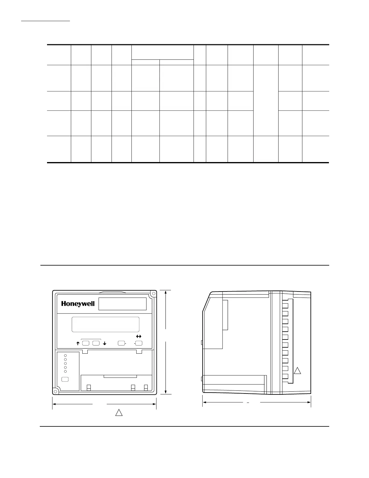
Fig. 1—Mounting dimensions of RM7800 Relay Module and Q7800A Subbase, in inches [millimeters].
BURNER CONTROL
POWER
PILOT
FLAME
MAIN
ALARM
RESET
SCROLL MODE
SAVE
5
[127]
5 [127]
M1984A
5 [133]
1
4
REMOVE ONLY FOR TERMINAL TEST ACCESS.
1
1
 Loading...

