RM7800E,G,L,M
SPECIFICATIONS
5 65-0117—2
ACCESSORIES:
Optional:
ControlBus 5-Wire Electrical Connector—part
no. 203541.
COMBUSTION SYSYEM MANAGER™—part
no. ZM7850A1001.
Communication Interface Base Unit—part no.
Q7700A1014.
Communication Interface ControlBus Module—part
no. QS7800A1001.
DATA CONTROLBUS MODULE™—part no.
S7810A1009.
Expanded Annunciator—part no. S7830A1005.
Flame Simulators:
—part no. 203659 UV Flame Simulator.
—part no. 123514A Rectification Simulator.
Keyboard Display Module—part no. S7800A1001.
Remote Reset Module—part no. S7820A1007
Remote Display Mounting Bracket—part no. 203765.
Remote Display Power Supply (13 Vdc): —part no.
203968A Plug-In.
Sixty-inch Extension Cable Assembly—part no.
221818A.
Tester—part no. A7800A1002.
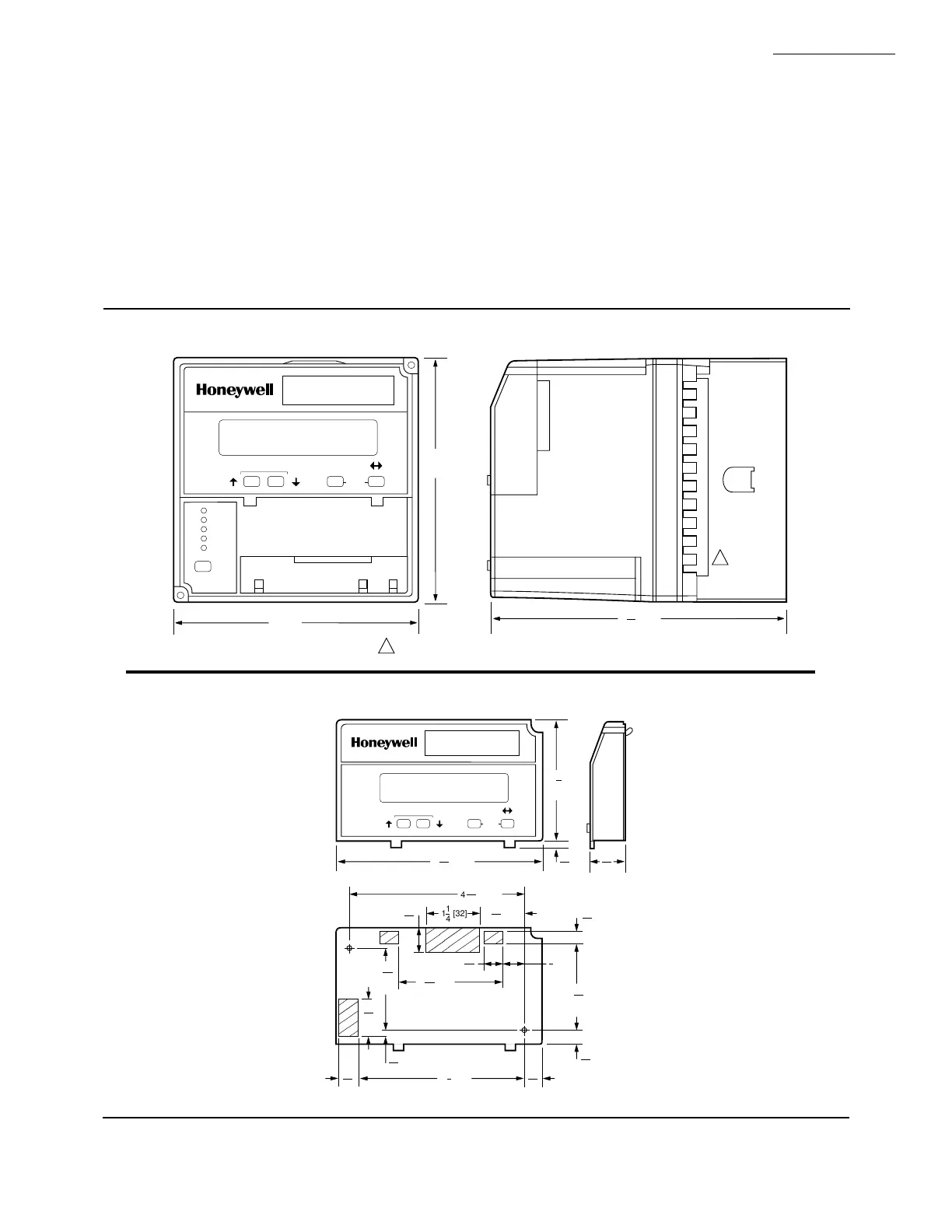
Fig. 2—Mounting dimensions of RM7800 Relay Module and Q7800B Subbase, in inches [millimeters].
POWER
PILOT
FLAME
MAIN
ALARM
RESET
SCROLL MODE
SAVE
5
[127]
5 [127]
M1985A
6 [155]
3
32
BURNER CONTROL
REMOVE ONLY FOR TERMINAL TEST ACCESS.
1
1
Fig. 3—Mounting dimensions of Keyboard Display Module, in inches [millimeters].
4 [123]
2
[69]
3
4
M5002A
5
32
[4]
29
32
[23]
27
32
SCROLL MODE
SAVE
BURNER CONTROL
1 [32]
1
4
4 [104]
3
32
19
32
[15]
29
32
[23]
7
16
[11]
[13]
1
2
2 [62]
7
16
1
[49]
15
16
2
[52]
1
32
5
16
[8]
5
16
[8]
5
32
[4]
3 [99]
7
8
15
32
[12]
13
32
[11]
1 [26]
1
32
 Loading...

