11 65-0106—2
c. Enclose scanner wires without armor cable in
metal cable or conduit.
d. Follow directions given in the flame detector
Instructions.
7. Maximum wire lengths:
a. For the RM7823A, the maximum length of
leadwire to the terminal inputs is 300 feet.
b. For the Flame Detector leadwires, the maximum
flame sensor leadwire length is limited by the
flame signal strength.
8. Make sure loads do not exceed the terminal ratings.
Refer to the label on the RM7823A or to the ratings in the
Specifications, see Table 1.
9. Check the power supply circuit. The voltage and
frequency tolerance must match those of the RM7823A. Do
not connect the RM7823A to a power supply circuit that can
have line voltage variations like on-off switching of heavy
loads. A separate power supply circuit may be required for the
RM7823A with the required disconnect means and overload
protection added.
10. Check all wiring circuits and complete the Static
Checkout, see Table 4, before installing the RM7823A on
the subbase.
11. Install all electrical connectors.
12. Restore power to the panel.
RM7823A
INSTALLATION
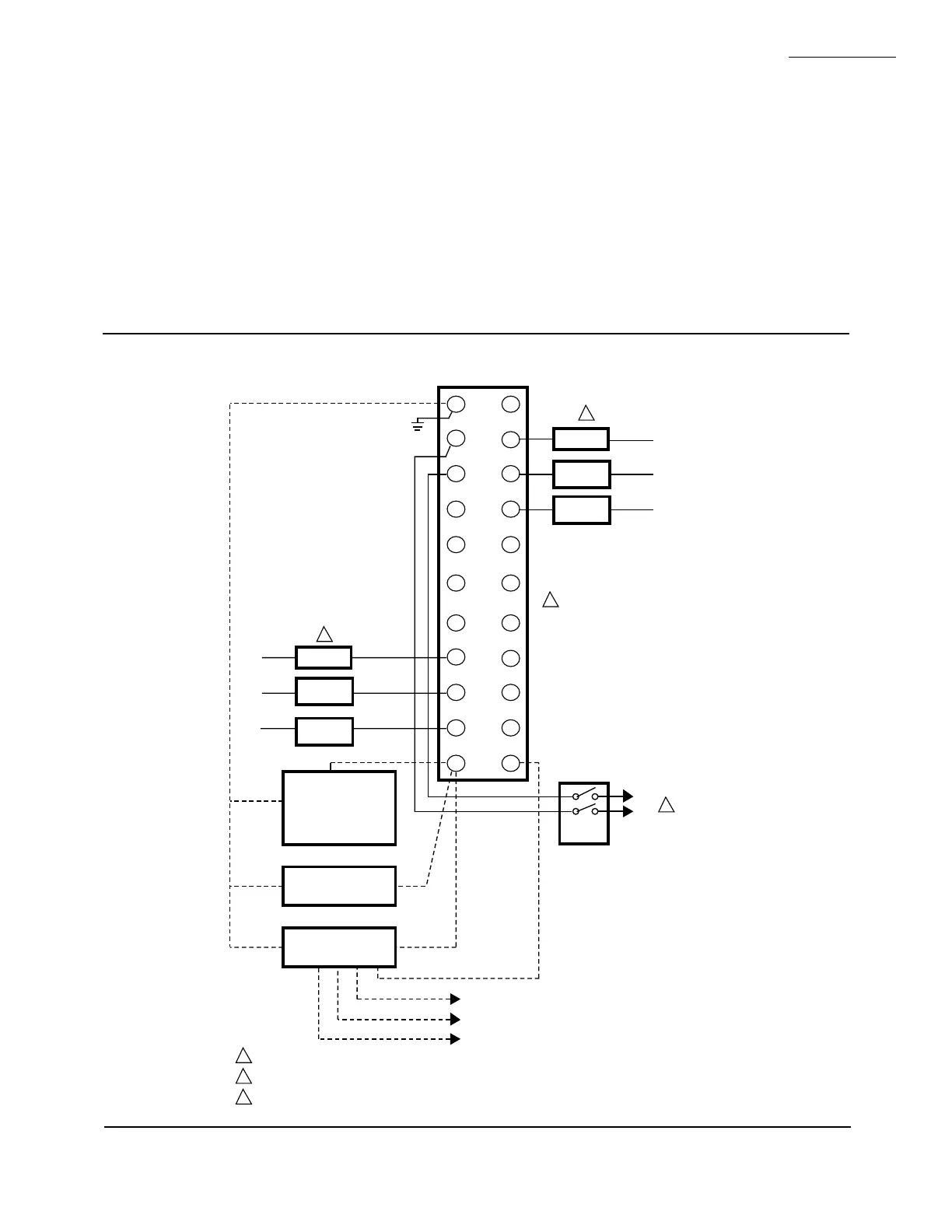
Fig. 7—Wiring the RM7823A
M5153
G
L2
3
4
5
6
7
8
9
10
F
(L1)
13
14
15
16
17
18
19
20
21
22
12
MASTER
SWITCH
NORMALLY
CLOSED
NORMALLY
OPEN
COMMON
RECTIFYING FLAME
ROD, RECTIFYING
PHOTOCELL,
OR INFRARED
(LEAD SULFIDE)
FLAME DETECTOR
C7027A, C7035A, OR
C7044A ULTRAVIOLET
FLAME DETECTOR
C7012A,C,E,F OR
C7076A ULTRAVIOLET
FLAME DETECTOR
120V, 60 Hz POWER SUPPLY. PROVIDE DISCONNECT MEANS AND OVERLOAD PROTECTION AS REQUIRED.
DO NOT CONNECT ANY WIRES TO UNUSED TERMINALS.
OUTPUTS SHOWN ARE WHEN THE DEVICE DOES NOT SEE FLAME.
L1
(HOT)
L2
1
OR
OR
BLUE
BLUE
WHITE
YELLOW
L2
WHITE
WHITE
BLACK
BLACK
L1
L2
1
Q7800
2
2
NORMALLY
CLOSED
NORMALLY
OPEN
COMMON
3
3
3
 Loading...
