9 65-0106—2
Installation
MICROCOMPUTER
RESET
PUSHBUTTON
STATUS
LEDs
POWER SUPPLY
PLUG-IN
FLAME
AMPLIFIER
RELAY
DRIVE
CIRCUIT
CONTROL
POWER
TEST
JACK
FIELD WIRING
INTERNAL WIRING
NC
COMMON
NO
NC
A1
120 Vac
FLAME SIGNAL
TEST
PROVIDE DISCONNECT MEANS AND
OVERLOAD PROTECTION AS REQUIRED.
OUTPUTS SHOWN ARE WHEN THE
DEVICE DOES
NOT
SEE FLAME.
L1
(HOT)
L2
3
A2
B1
10
8
9
14
F
G
22
1
COMMON13
NO15
L2
OPTIONAL KEYBOARD
DISPLAY MODULE
REMOTE
RESET
DDL
DDL
COMMUNICATIONS
RS485
1
2
3
1
M9259
9K
B2
9K
2
2
RM7823A
INSTALLATION
!
WARNING
FIRE OR EXPLOSION HAZARD CAN
CAUSE PROPERTY DAMAGE, SEVERE
INJURY, OR DEATH
Verification of safety requirements must be per-
formed each time a control is installed on a burner
to prevent possible hazardous burner operation.
WHEN INSTALLING THIS PRODUCT…
1. Read these instructions carefully. Failure to follow
them could damage the product or cause a hazardous
condition.
2. Check the ratings given in the instructions and on
the product to make sure the product is suitable for your
application.
3. Installer must be a trained, experienced flame safe-
guard service technician.
4. After installation is complete, check out the product
operation as provided in these instructions.
!
CAUTION
1. Disconnect the power supply before begin-
ning installation to prevent electrical shock and
equipment damage. More than one power sup-
ply disconnect may be involved.
2. Wiring connections for the RM7823A are
unique; therefore, refer to Fig. 6 or the correct
Specifications for proper subbase wiring.
3. Wiring must comply with all applicable codes,
ordinances and regulations.
4. Wiring, where required, must comply with
NEC Class 1 (Line Voltage) wiring.
5. Loads connected to the RM7823A must not
exceed those listed on the RM7823A label or
the Specifications, see Table 1.
6. All external timers must be listed or component
recognized by authorities who have jurisdiction
for the specific purpose for which they are used.
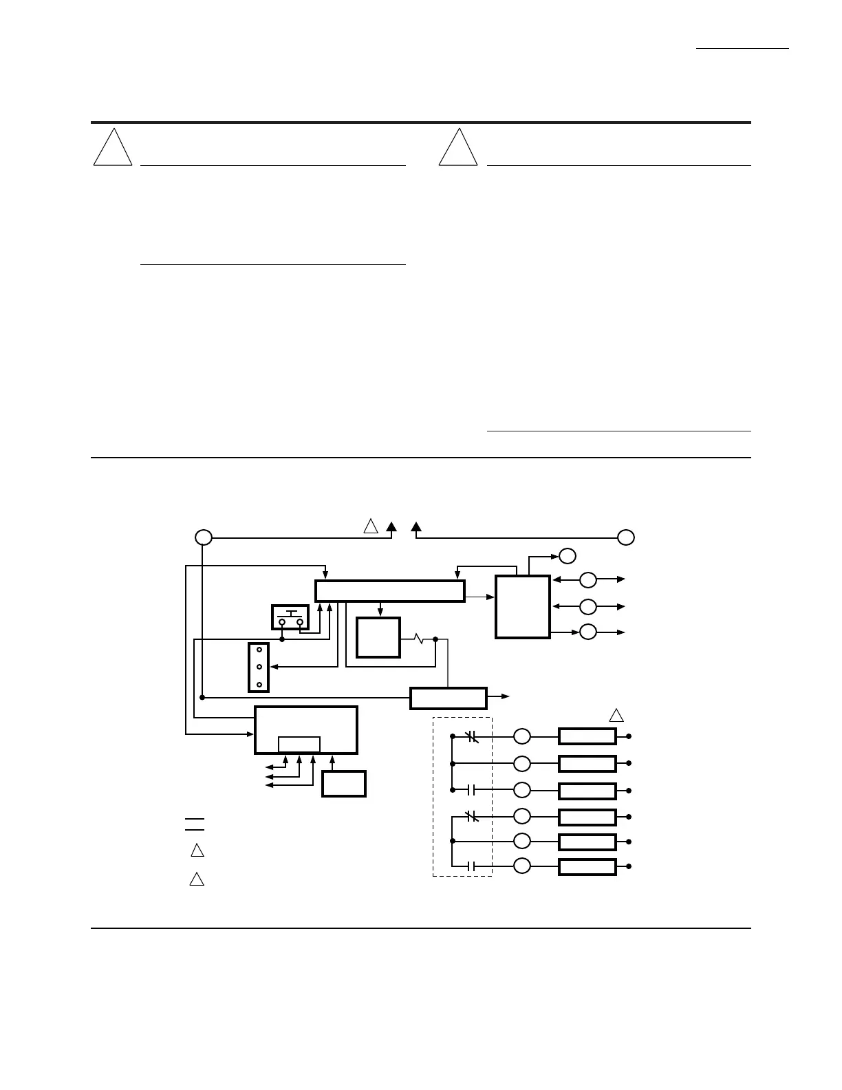
Fig. 6—Internal block diagram of the RM7823A (see Fig. 7 for detailed wiring instructions).
 Loading...
