65-0106—2 14
RM7823A
OPERATION
Operation
TABLE 3—LED SEQUENCE STATUS
DISPLAY INFORMATION.
Burner Sequence LEDs Energized
STANDBY POWER, FLAME and ALARM
RUN POWER, FLAME and ALARM
RESET/ALARM POWER, FLAME and ALARM
TEST
See Table 6 for further details of Hold conditions.
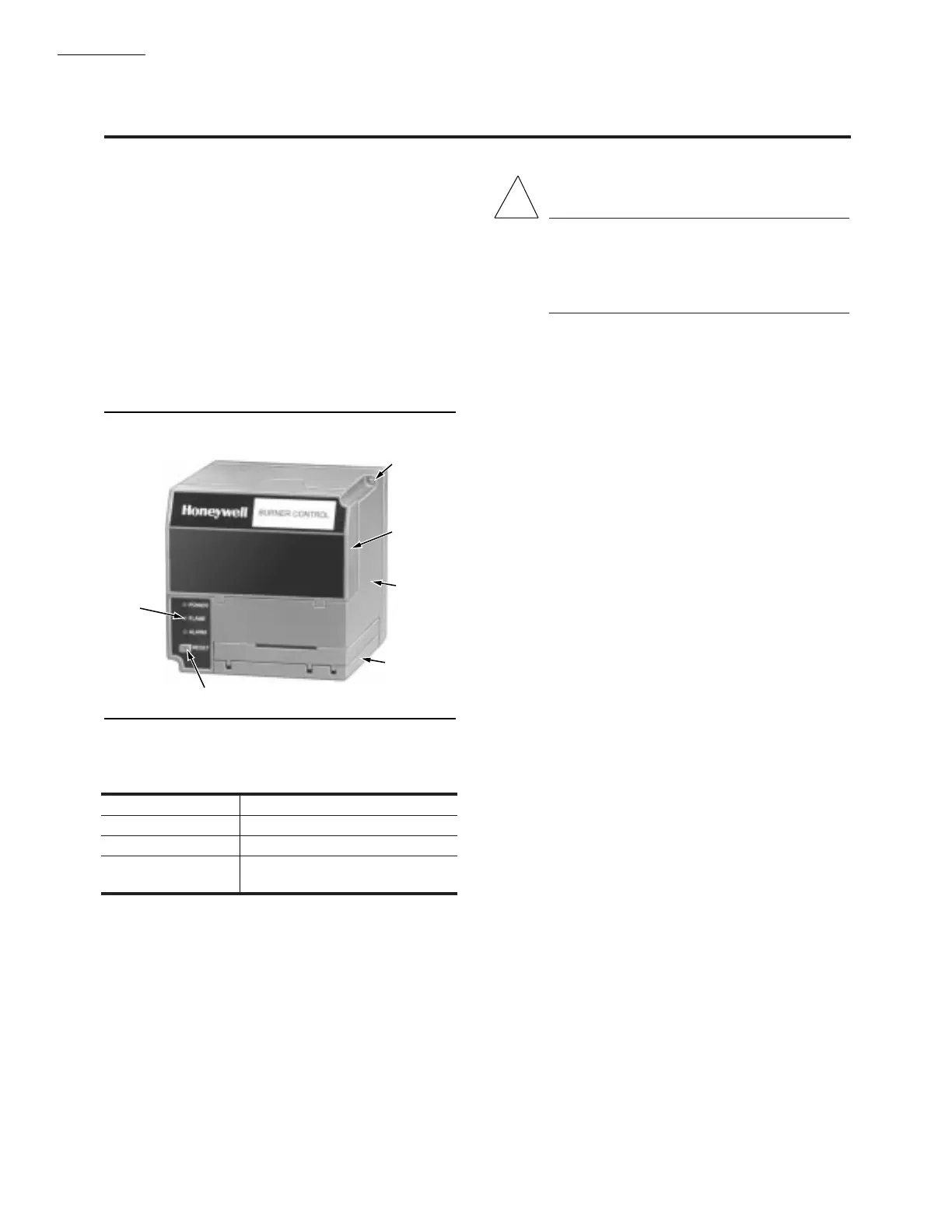
Fig. 13—Sequence status LEDs.
Sequence of Operation
The RM7823A has the following operating sequences,
see Fig. 13 and Table 3.
STANDBY
The RM7823A is ready to respond to sighting of a flame
or flame simulating condition. The green POWER LED will
blink every four seconds, signifying the RM7823A is
doing internal hardware checks.
RUN
The RM7823A pulls in the two internal spdt relays and
turns on the FLAME LED when a flame or flame simulating
condition exists. The RM7823A is now in RUN.
STATIC CHECKOUT
CAUTION
1. Use extreme care while testing the system. Line
voltage is present on most terminal connections
when power is on.
2. Open the master switch before installing or re-
moving a jumper on the subbase.
After checking all wiring, perform this checkout before
installing the RM7823A on the subbase. These tests verify
that the Q7800 Wiring Subbase is wired correctly.
NOTE: Do not perform a dielectric test with the RM7823A
installed. Internal surge protectors will break down and
conduct a current. This could cause the RM7823A to fail
the dielectric test or possibly destroy the internal light-
ning and high current transient protection components.
EQUIPMENT REQUIRED
1. Voltmeter (20 kohm/volt minimum sensitivity) set on
the 0-300 Vac scale.
2. Two jumper wires, no. 14 wire, insulated, 12 inches
(304.8 mm) long, with insulated alligator clips at both ends.
GENERAL INSTRUCTIONS
1. Perform all applicable tests listed in Static Checkout,
Table 4, in the order listed.
2. For each test, open the master switch and install the
jumper wire(s) between the subbase wiring terminals listed
in the Test Jumpers column of Table 4.
3. Close the master switch before observing operation.
4. Read the voltage between the subbase wiring termi-
nals listed in the Voltmeter column of Table 4.
5. If there is no voltage or the operation is abnormal,
check the circuits and external devices as described in the
last column.
6. Check all wiring for correct connections, tight termi-
nal screws, correct wire, and proper wiring techniques.
Replace all damaged or incorrectly sized wires.
7. Replace faulty controllers, limits, interlocks, actuators,
valves, transformers, motors and other devices as required.
8. Obtain normal operation for each required test before
continuing the checkout.
9. After completing each test, be sure to remove the test
jumper(s).
!
CAPTIVE
MOUNTING
SCREW
DUST
COVER
RELAY
MODULE
FLAME
AMPLIFIER
RESET PUSHBUTTON
SEQUENCE
STATUS
LEDS
M7889
 Loading...
