13 65-0106—2
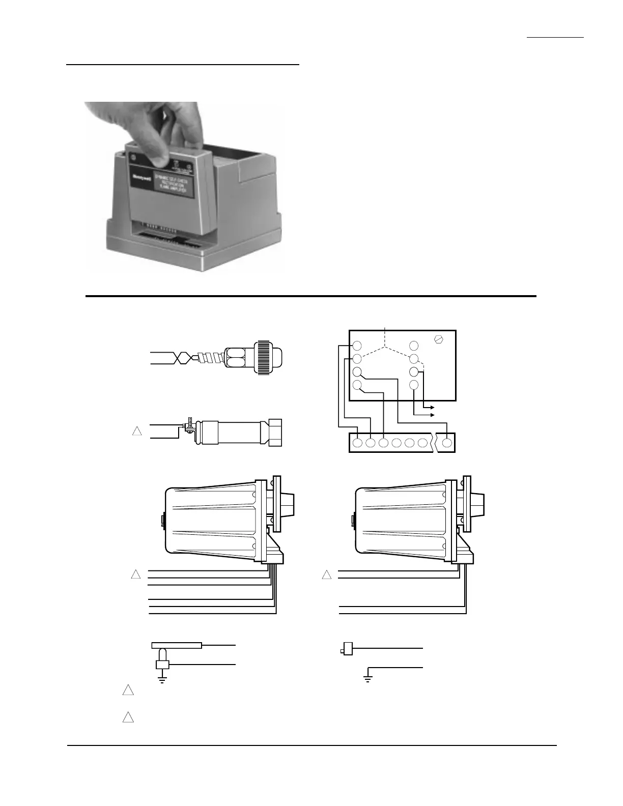
Fig. 11—Flame signal amplifier mounting.
RM7823A
ASSEMBLY
INSTALLING THE FLAME DETECTOR
NOTE: Table 2 and Fig. 12 list the flame detection systems
available for use with the RM7823A. Make sure the
correct combination of amplifier and flame detector(s)
is used.
Proper flame detector installation is the basis for a reliable
installation. Refer to the Instructions packed with the flame
detector and the equipment manufacturer instructions.
Keep the flame signal leadwires as short as possible from
the flame detector to the wiring subbase. Capacitance in-
creases with leadwire length, reducing the signal strength.
The maximum permissible leadwire length depends on the
type of flame detector, leadwire and conduit. The ultimate
limiting factor in the flame detector leadwire is the flame
signal, see Table 5.
Fig. 12—Flame detector wiring.
BLUE
YELLOW
WHITE
WHITE
BLACK
BLACK
F
G
22
L2
L1
L2
BLUE
WHITE
F
G
WHITE
BROWN
F
G
INFRARED (C7015)
ULTRAVIOLET (C7027/C7035/C7044)
SOLID STATE SELF-CHECKING
ULTRAVIOLET (C7012E,F)
BLUE
YELLOW
BLACK
BLACK
F
G
L1
L2
SOLID STATE
ULTRAVIOLET (C7012A,C)
1
2
2
F G
4
5
3
L2
C7076A,D ULTRAVIOLET DETECTOR
5
22
6
SHUTTER
G
SHUTTER
F
1
8
2
7
7800 SERIES
L1
L2
3a
3b
REMOTE
SENSOR
2b
2a
EARTH
GROUND
C7076A
OR
C7076D
TERMINAL
BLOCK
L2 (COMMON)
L1 (HOT)
G
F
X
X
FLAME ROD
G
F
X
X
PHOTOCELL
M1969B
1
FLAME DETECTOR LEADS ARE COLOR CODED. THE BLUE LEAD MUST BE CONNECTED TO THE F TERMINAL AND THE WHITE
MUST BE CONNECTED TO THE G TERMINAL. THE UV SENSING TUBE IS POLARITY SENSITIVE. REVERSING THE LEADS EVEN
MOMENTARILY CAN DAMAGE OR DESTROY THE UV TUBE.
FLAME DETECTOR LEADS ARE COLOR CODED. THE BLUE LEAD MUST BE CONNECTED TO THE F TERMINAL AND THE YELLOW
MUST BE CONNECTED TO THE G TERMINAL. THE UV SENSING TUBE IS POLARITY SENSITIVE. REVERSING THE LEADS EVEN
MOMENTARILY CAN DAMAGE OR DESTROY THE UV TUBE.
2
 Loading...
