Page 12 of 18 APHITEMPCON001-11-04
1 2 3
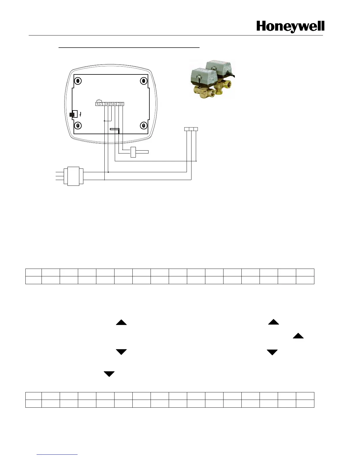
VC-7934
COM
HOT
IN PUT
BROWN
4 - 20 mA
2 - 10 VDC
WIRING DIAGRAM T2798I2000 WITH VC-7934
BLACK
BLUE
A/O
D/I
Pt1000
sensor
0VAC
24VAC
50 / 60 Hz
OVAC
110VAC
230VAC
PT1000
REMOTE
SENSOR
0VAC
24VAC
TRANSFORMER
Installer Set-Up:
1. Power ON/OFF :
- Connect the main power. Display will show “Honeywell”, as shown in fig.1, for 5 Sec.
Then display will show the Process value
(PV) and Set point (SP) as shown in fig.2
H o n e y w e l l
Fig. 1
2. Set Point configuration (SP):
- Press key one time to step up the set point value by 0.1°C. If pressed
continuously for more than ten steps then the value will increment by the step of 1.0°C
up to 60.0°C (for internal sensor) or 110.0°C (for external sensor). Release key to
stop the increment of temp set value.
- Press key one time to step down set point value by 0.1°C. If pressed
continuously for more than ten steps then the value will decrement by the step of 1.0°C
up to 10.0°C (for internal sensor) or –20.0°C (for external sensor). Release
key to stop decrement of temp set value.
- Press “ENTER” key to save the set value.
P V : 3 0 . 2 ° C
S P : 1 9 . 0 ° C
Fig. 2

 Loading...