Application 3: 2 pipes 1 stage Heat or 1 stage Cool
MCO wiring diagram
Application 2: 2 pipes Cool only wiring diagram
1 Pull wires through wire hole.
Loosen screw terminals, insert wires into terminal
Block, then retighten screws.
Terminal Designations
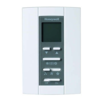
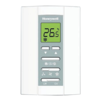
Install the thermostat about 5 feet (1.5m) above the
oor in an area with good air circulation at average
temperature.
Do not install in locations where the thermostat can
be affected by:
• Drafts or dead spots behind doors and in corners
• Hot or cold air from ducts
• Sunlight or radiant heat from appliances
• Concealed pipes or chimneys
• Unheated/uncooled areas such as an outside wall
Installation & Commissioning
Figure 0-2 Typical wiring for 3-wire control in 2 pipe cooling only
Figure 0-3 Typical wiring for 3-wire control in 2 pipes 1H1C
Wiring diagram
Application 1: 2 pipes heat only wiring diagram
Figure 0-1 Typical wiring for 3-wire control in 2 pipe heating only
Terminal Description
L Line voltage Power
Ch/Cc Valve close
W/Y Valve open
N Line voltage ground
Gl Low speed fan relay
Gm Medium speed fan relay
Gh High speed fan relay
Sc Ground for remote sensor
Rs Remote sensor
Heat valve
Fan
remote sensor
Cool valve
Fan
remote sensor
valve
Fan
remote sensor
 Loading...