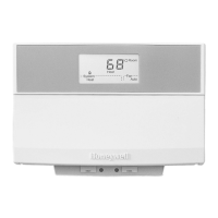
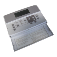
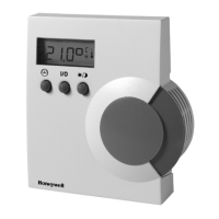
T7560A,B,C DIGITAL WALL MODULES
95-7620-4
EN1B-0146GE51 R0303
2
INSTALLATION
Mount the wall module on an inside wall approximately 54 in.
(1.3 m) from the floor (or as specified on the installation
drawings) to allow exposure to the average zone
temperature. Do not mount the wall module on an outside
wall, on a wall containing water pipes or near air ducts. Avoid
locations that are exposed to discharge air from registers or
radiation from lights, appliances, or the sun.
The DWM is furnished with a terminal block; all field wiring
connections are made to these eight terminals.
The DWM has to be mounted in vertical position with the
LCD display to the top.
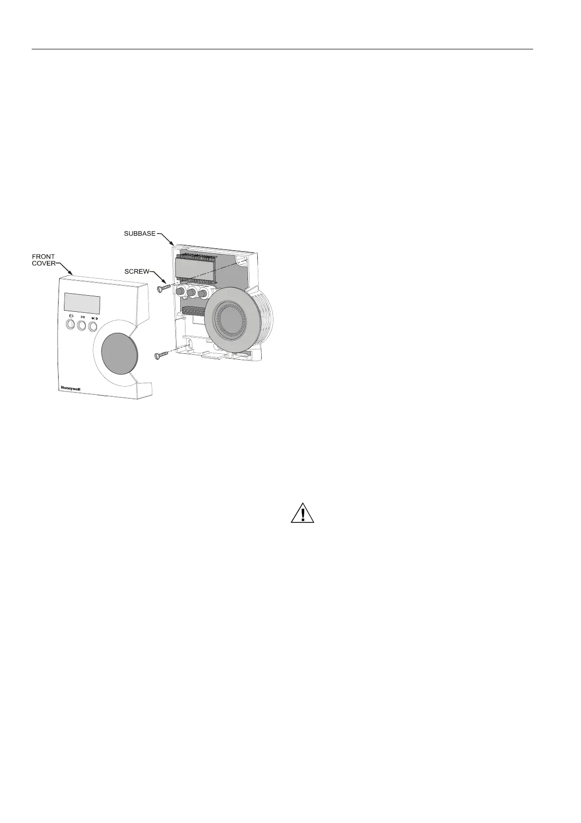
Mount the subbase directly on a wall (see Fig. 3) using the
type of screws appropriate for the wall material.
Fig. 3. Mounting of DWM (T7560A,B shown)
See Fig. 6 for T7560A,B,C mounting dimensions.
Wiring
Wire the terminal blocks as follows:
1. Strip 3/16 in. (5 mm) of insulation from the conductor.
2. Insert the wire in the required terminal location and
tighten the screw to complete the termination.
IMPORTANT
Deviation from this rule can result in improper
electrical contact. See Fig. 4.
3. Verify DWM is wired according to Fig. 4.
NOTE: For specific wiring requirements, see the following
Power section.
Power
The DWM can be powered either via the 5 V LED input
(terminal 5) or via the 24 Vac/dc input (terminal 8).
IMPORTANT
The DWM can be powered only via terminal 5 with
those controllers listed in Table 2, and if a
SW version listed in Table 2 or higher is installed.
If the DWM is powered via terminal 5, the Excel 10
controller must be configured for LCD_DISPLAY
(LED output continuously ON).
NOTE: The 24 Vac power supply is needed only with the
T7560B DWM (for the humidity sensor).
Alternatively, a DC voltage source with 5...12 V can
be connected to terminal 5 (see IMPORTANT note
above).
Alternatively, a DC voltage source with 18...30 V
(e.g. 22 Vdc from W7750 CVAHU) can be
connected to terminal 8.
Input ratings
Terminal 5:
min. 5 Vdc I
max
3 mA
max. 12 Vdc I
max
5 mA
or LED output of any Excel 10 controller
Terminal 8:
24 Vac from controller; I < 5 mA
or
18...30 Vdc; I < 5 mA
Controllers with the following output ratings can be
connected to terminal 5
(ratings are met by all Excel 10 controllers):
• 5 V with 389 ohms
• 4.3 V with 100 ohms
• 14.3 V with 1.5k ohms
Use up to 16 AWG (1.5 mm
2
) with a minimum of 18 AWG
(1.0 mm
2
) wire for connecting 24 Vac power to terminal 8.
CAUTION
Low Voltage Equipment.
Risk of equipment damage.
The 24 Vac power source for the DWM must be a
Class II Power Source. To conform to Class II
restrictions, transformers must not be larger than
100 VA. A transformer that is CE certified and meets
the Low Voltage Device (LVD) requirements must be
used in Europe for all installations of this product.
The DWM power usage is < 0.5 VA at 24 Vac. The DWM
does not require a dedicated transformer. The DWM can get
power from any convenient location in the 24 Vac power
circuit.
The 24 Vac power can come from the 24 Vac power
terminals on the nearest controller or directly from a 24 Vac
transformer, whichever is closer.
 Loading...