T7560A,B,C DIGITAL WALL MODULES
95-7620-4
EN1B-0146GE51 R0303
4
CONFIGURATION (T7560A,B)
After installation, the T7560A,B DWM must be configured in
order to perform as desired. This is done by using the
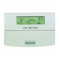
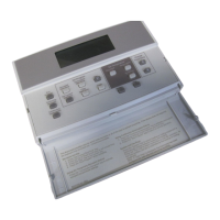
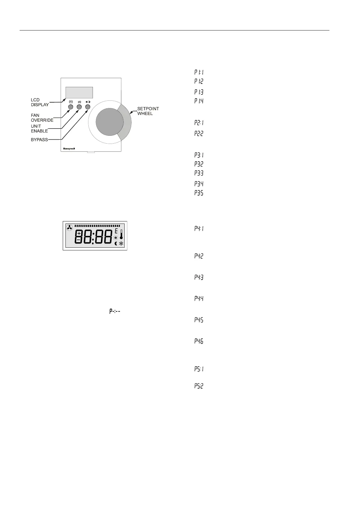
buttons and the setpoint wheel (see Fig. 7).
Fig. 7. Control elements of T7560A,B DWM
Normal Operating Mode
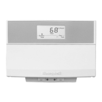
After the DWM is powered up by the controller, it will display
the room temperature and will operate as configured by
default; the respective default setting is marked with an
asterisk in the following.
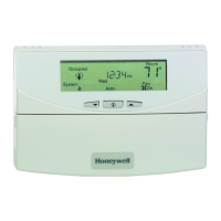
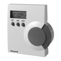
After power-up, all display segments are switched on for
approx. one second (see Fig. 8).
AUTO
MANU
PROG
Fig. 8. Display of all segments after power-up
Entering Configuration Mode
1. Press FAN OVERRIDE for at least 5 seconds.
2. Press UNIT ENABLE, then release FAN OVERRIDE,
hold UNIT ENABLE for at least 5 seconds.
3. Release UNIT ENABLE.
RESULT: The display shows
and the DWM is
ready for configuration (see below).
4. Press and hold FAN OVERRIDE while turning the
setpoint wheel to select the parameter number.
RESULT: The parameters with their currently set
values are displayed; the
≡ behind the
value indicates the currently set value (see
below for values).
5. Release FAN OVERRIDE and turn the setpoint wheel to
select the parameter value.
6. Confirm selection by pressing UNIT ENABLE.
7. Repeat steps 4 to 6 to configure next parameter, or
press BYPASS to leave the configuration mode.
NOTE: After approx. 10 seconds without further action, the
DWM automatically falls back to normal mode.
P1 Setpoint Type Setting
Scale Type Setting
•
Fahrenheit relative
•
Fahrenheit absolute
∗ Centigrade relative
•
Centigrade absolute
P2 Room Temperature Setting
•
Do not display room temperature (setpoint, only)
∗ Display room temperature
P3 Bargraph Use Setting
•
No Fan
•
Auto, Off, On
•
Auto, Off, 2 Speeds
∗ Auto, Off, 3 Speeds
•
Bargraph shows humidity (each segment
represents 4% rel. humidity; no fan speed
available)
P4 Controller Type Setting
∗ New LCD signaling from controller
(only with controllers and SW versions as listed in
Table 2 or higher; set Excel 10 controller to
LCD_DISPLAY)
•
LED override mode from controller,
US signaling (100 ms pulses);
with contr. W7750, W7751, W7753, W7761, XL12
•
LED override mode from controller,
European signaling (500 ms pulses);
with contr. W7752, W7762, W7763, XL12
•
LED occupancy mode from controller,
US signaling (“Japan Mode”; set Excel 10
controller to LED_OCCUPANCY)
•
LED occupancy mode from controller,
European signaling (500 ms pulses);
with contr. W7752, W7762, W7763, XL12
•
Excel 500 signaling from controller
(10 V, 8 V, 6 V)
P5 Pin 4 (Bypass/Fan) Grounding
•
Pin 4 not shorted to GND if override is pressed
(UV-controller, W7753)
∗ Pin 4 shorted to GND if override is pressed
 Loading...