T8635L MICROELECTRONIC COMMUNICATING PROGRAMMABLE THERMOSTAT
3 69-1331—5
CAUTION
Voltage Hazard.
Can cause electrical shock or equipment
damage.
Disconnect power before beginning installation.
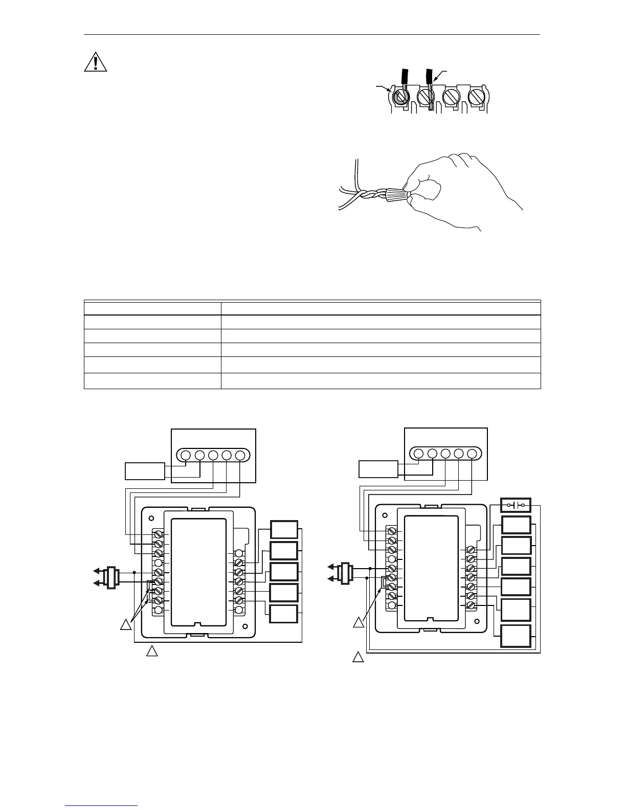
1. Loosen the terminal screws on the wallplate and
connect the system wires. See Fig. 3 and 4.
IMPORTANT
Use 18-gauge color-coded thermostat cable for
proper wiring. Shielded cable is not required.
2. Securely tighten each terminal screw.
3. Push excess wire back in the hole.
4. Plug the hole in the wall with non-flammable insu-
lation to help prevent drafts from adversely affect-
ing thermostat operation.
Fig. 3. Correct wiring technique.
Fig. 4. Using wire nut to pigtail a
connection when three or more wires
are terminated at one terminal.
Table 2. Terminal Designations.
Fig. 5. T8635L/W8635A with
Outdoor Temperature Sensor.
Fig. 6. T8635L/W8635B with
Outdoor Temperature Sensor.
M482
OR WRAPAROUND
NSERTION STRIP
/16 IN. (11 MM).
FOR STRAIGHT INSERTION
STRIP 5/16 IN. (8 MM).
WIRE NUT
M1337
T8635L Terminal Designations Function
1 Data – Connect to terminal 1 on W8835 or W8635.
2 Power – Connect to terminal 2 on W8835 or W8635.
3 Power – Connect to terminal 3 on W8835 or W8635.
OT
Outdoor Temperature Sensor
a
a
Use optional C7089B Outdoor Temperature Sensor.
OT
Outdoor Temperature Sensor
a
L1
(HOT)
L2
COOL 1
RELAY
HEAT 2
RELAY
FAN
RELAY
OT
OT
2
1
3
FACTORY INSTALLER JUMPERS.
M1342
C7089B
OUTDOOR
TEMPERATURE
SENSOR
1
T8635L
HEAT 1
RELAY
W8635A
C
R
R
H
R
C
1
2
3
Y2
W2
Y1
G
W1
COOL 2
RELAY
1
SYSTEM
TRANSFORMER
EM. HT.
RELAY
AUX. HT.
RELAY
FAN
RELAY
OT
OT
2
1
3
FACTORY INSTALLER JUMPER.
M1343
C7089B
OUTDOOR
TEMPERATURE
SENSOR
1
T8635L
COMP.
RELAY
W8635B
C
R
R
H
1
2
3
O
B
AUX
E
G
W1/Y1
COOL
CHANGE-
OVER
L
HEAT
CHANGE-
OVER
COMPRESSOR
MONITOR
L1
(HOT)
L2
1
SYSTEM
RANSFORMER
 Loading...