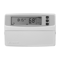
T8635L MICROELECTRONIC COMMUNICATING PROGRAMMABLE THERMOSTAT
5 69-1331—5
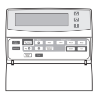
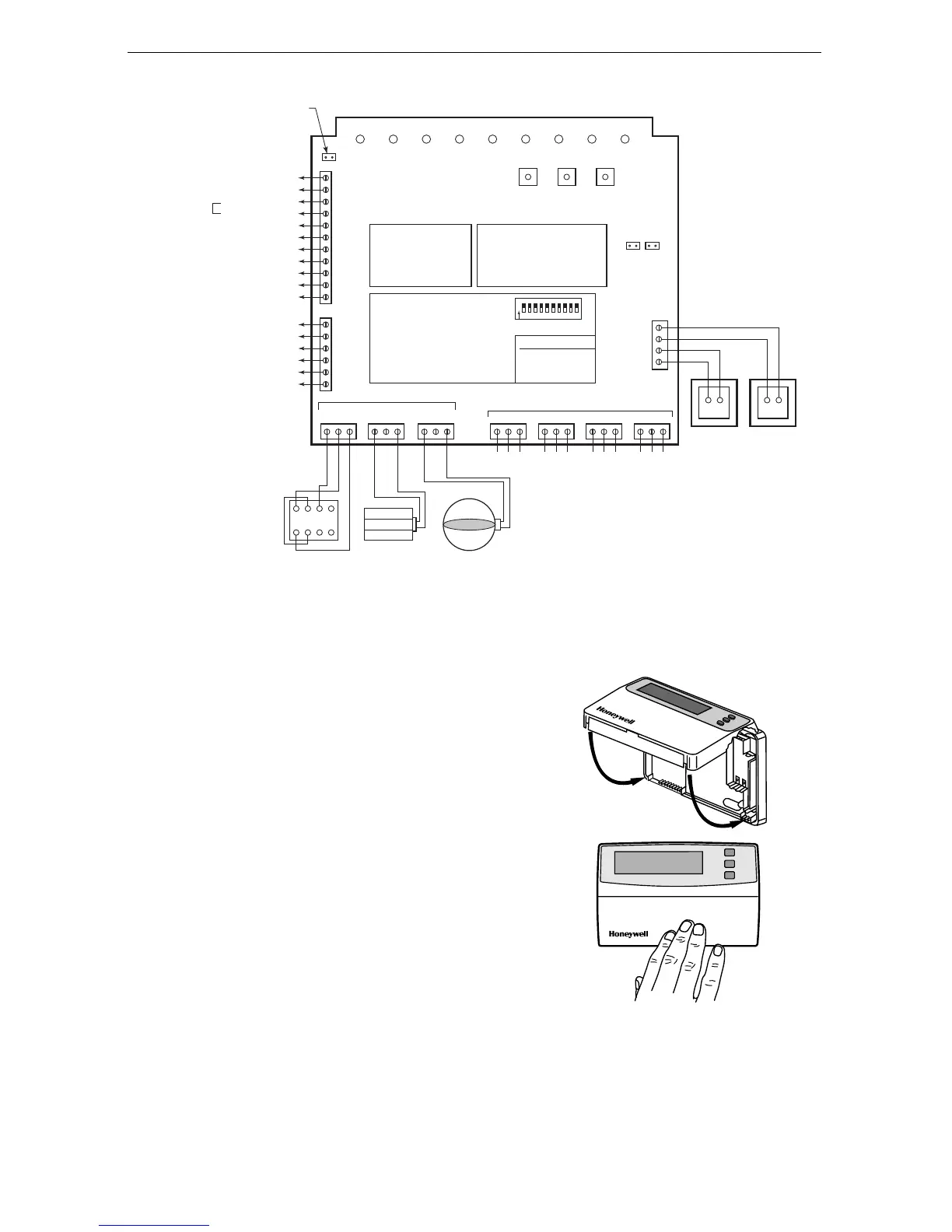
Fig. 8. W8835 EnviraZone Panel wiring.
Mounting Thermostat on Wallplate
NOTE: To remove the thermostat from the wall, first
pull out at the bottom of the thermostat;
remove the top last.
1. Engage tabs at the top of the thermostat and wall-
plate. See Fig. 9.
2. Press the lower edge of the case to close and
latch.
Fig. 9. Mounting thermostat on wallplate.
ZONE DAMPER MOTORS
M1 - common
M4 - power open
M6 - power closed
PURGE
OVERRIDE
BOOTDISCOVERY
T2
T1
C
R
This diagram shows the typical
equipment, thermostat, and
damper motor connections.
For specific wiring,
refer to the Installation
Instructions.
CR
24 VAC, 40 VA
Optional
Transformer
(required if
system load
is greater
than single
transformer
output.)
CR
24 VAC, 40 VA
Panel
Transformer
Damper
XFRM
Enviracom
XFRM
32003618-00
REV. B
HEAT COOL PURGE FAN EM. HT. COMM ZONE 1 ZONE 2 ZONE 3
HVAC Equipment
L
C
Rh
Rc
W1/E
HP Fault
HP Fault Common
Heating Transformer
24 VAC
Equipment
Cooling Transformer
irst Stage Heating/Emergency Heat Relay
W2
Second Stage Heating Relay
W3/AUX
Third Stage Heating/Auxiliary Heat Relay
Y1
First Stage Cooling Relay
Y2
Second Stage Cooling Relay
G
Fan Relay
Auxiliary Equipment
HUM
HUM
DHUM
DHUM
VENT
Humidifier
Humidifier
Dehumidifier
Dehumidifier
Ventilator
VENT
Ventilator
O/B
Reversing Valve (Cooling/Heating)
Golden Valley, MN 55422
www.honeywell.com/yourhome
LED STATES:
Heat LED Heating Mode
Cool LED Cooling Mode
Purge LED Purge Mode
Fan LED Fan Mode
Em Heat LED Em Heat Mode
COMM LED Communications
ZONE LEDS:
On Damper open or opening
Off Damper closed or closing
MOMENTARY PUSH BUTTONS
Boot Clears Microprocessor
Purge Override Bypass Purge Mode
Discovery Initiates Discovery Mode
Single transformer heating/cooling
systems require a jumper to be
installed connecting R
H
and R
C
(factory installed).
Power-open/
Power-closed
(Opposed Blade
Damper Motors)
Power-closed/
Spring-open
(Model ZD)
Power-closed/
Spring-open
(Model ARD)
DIP SWITCH SETTINGS
1 SEE TABLE ON OFF
2 SEE TABLE 1 0
3 ENVIRACOM FURN NO YES
4 PURGE TIME 2.0 MIN 3.5 MIN
5 PURGE FAN HVAC PANEL
6 PURGE DAMPER NO CHG OPEN
7 # COMP STAGES 1 2
8 HEAT FAN HVAC PANEL
9 HP CHANGEOVER O B
10 UNUSED
#1 #2 CONV HT STG
1 1 1
1 0 2
0 1 3
0 0 HP
1
O
N
2 3 4 5 6 7 8 9 10
M6
1
4
X
Z
2
5
3
6
M4 M1
ZONE 1
M6 M4 M1
ZONE 2
DAMPERS
ENVIRACOM BUS
M6
M4 M1
ZONE 3
1 2 3 1 2 31 2 3 1 23
123
(can connect to any set of 1,2,3 terminals)
123123 12
3
XFRM
Jumpers
Attach jumpers
(factory installed
in open position)
if using only
one transformer.
TM
M20850A
M1462
PRESS LOWER
EDGE OF CASE
TO LATCH.
ENGAGE TABS
AT TOP OF
THERMOSTAT
AND WALLPLATE.
A.
.
 Loading...